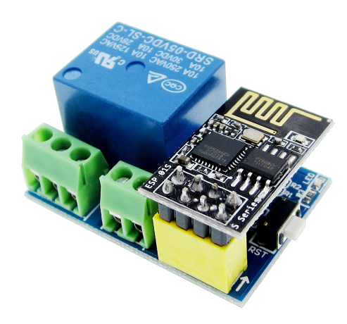
 In an earlier post, I discussed how to quickly make a one channel WiFi relay with a relay module an ESP8266-01 and some Dupont cables.
In a later post, I showed how to make a 4 channel WiFi relay with an ESP8266-01 and a 4 channel relay board.
Both posts were a consequence of 2 videos by Ralph Bacon, discussing his slightly disappointing adventures with 2 commercially available Wifi relay boards, based on an ESP8266-01.
Out of interest I bought one of those boards -knowing the shortcomings Ralph pointed out- that I presumed I could fix.
The board comes with an ESP8266-01s. It has a Reset button, which isn’t really useful. The GPIO0 drives the relay through a 7002 FET, GPIO2 drives an LED and TX and Rx are not connected to anything.
The crux of this board is that it is really designed for the ESP8266-01S, although it can be made to work with the regular ESP8266-01. The ESP8266-01S is a version that already has pull-ups on GPIO0 and GPIO2, albeit that one of those pullups is through an onboard LED. The regular ESP8266-01 does not have these pull ups and the relay board does not provide them.
The relay module uses only one pin, GPIO0. It is connected to the gate of a 2007 FET that switches the relay and that is exactly where the problem starts. During startup, the ESP needs GPIO0 to be HIGH, unless you want to go to flash mode, when it needs to be LOW.
But as the ESP8266-01S correctly pulls pin GPIO0 HIGH, the relay will immediately be activated at startup. Hence he designer added a pull down resistor. Due to the presence of the Pull up on GPIO0 on the ESP8266-01 board, that needed to be a very strong pull down resistor and a 2k resistor was chosen. But now the GPIO0 pin is pulled LOW at startup, putting it in flash mode.
There are some simple solutions for this:
- remove the 2k resistor. However this will activate the relay at start up.
- reroute the triggersignal to come from pin GPIO1 (Tx) or GPIO3 (Rx) (but you still need to remove the 2k resistor)
The latter solution is fairly simpel because of the long PCB trace going from GPIO0 to the gate of the FET
Strange, this July 5th dated post popped up in my mail just now. Anway, I love this small board, but modified it in a slightly different way, keeping the 01s BTW.
– removed the 2K pullup
– cut the trace between RST and the switch
– cut the trace between GPIO0 and the relay driver
– soldered a thin wire (I use transformer wire) between the switch and GPIO0
– and another between the relay driver and GPIO2
End result:
– close match with a Sonoff Basic
– switch is now an on-off switch
What isn’t solved is the pull up on GPIO2, activating the relay, and yes, it’s quite the modification for such a small board. But the form factor, nice edge blocks and the on board LDO and MOSFET makes it worth it IMHO.
Not so strange,I had written it a while ago, but kept off on publishing it coz I wanted to add a picture of the modification, but just didnt get around to making it, and by now it is built in somewhere, so i just went ahead and published it.
Indeed, the 2k removal is essential. Your total modification is quite handy, in regards of making it behave close to a sonoff basic.
I rerouted the track to Rx to avoid the relay going high on startup, eventhough that would only be a minor inconvenience. Once in place it would work uninterrupted for long time
For use of the Rx pin need to “tell” the pin to behave like a GPIO with
pinMode(3,FUNCTION_3);.Alltogether definitely a worthwhile module and not so hard to modify.
There are a few more of those esp-01 add on modules that are quite handy. Currently working with a smal neopixel driver board for the esp-01.