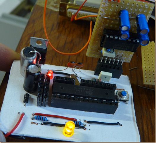
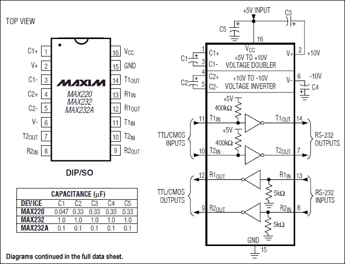
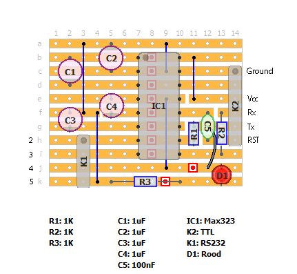
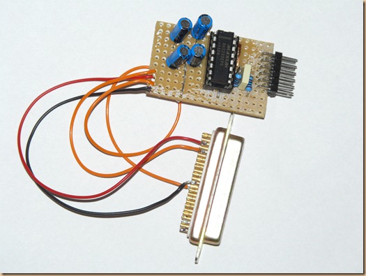
A connection between a computer and a self build Arduino (or other microcontroller) is easy to make with a MAX232 chip. The figure below is an almost classic design. It is according to the october 2002 revision of the datasheet: C4 is connected between pin2 and earth, while in other designs it is connected between pin 2 and Vcc (kathode on Vcc). This circuit just worked for me. I guessed that if pin 2 has a higher potential than Vcc, it also has a higher potential than ground. In some circuits you will also find it connected between pin 2 and 6
In principle you could do with only 2 signals (Tx and Rd), but I have added a reset that is connected to the RTS signal on the subD connector (Via the Max232 of course) 
Just for some clarification: Normally with a serial communication set up, the Tx signal of one device, is connected to the Rd pin of the other device. In this circuit, that is taken care of on the SubD connector: Pin 3 is the Tx signal, that goes to the RdIn (pin 8) of the chip. It is converted in voltage in the chip, then goes to RdOut on pin 9. That pin –though called Rd- then goes to the Rd pin on the Arduino/Atmega/Pic. The connection between Tx and Rd already has been made, no need to switch that again.
Same for the Tx signal of the microprocessor: It attaches to pin10 on the Max232, is converted and appears on pin 7 of the chip and then is brought to the Rd pin on the SubD connector. The DB9 plug in th epicture is a female plug looked at from the solder side.
If for any reason one would prefer to use an old SubD25 serial connector, the table below shows the corresponding pins between the two. To make things a bit confusing both pin 2 and 3 have exactly opposite functions on these connectors.
| DB9 | Signal | DB25 |
| 1 | DCD | 8 |
| 2 | Rd | 3 |
| 3 | Tx | 2 |
| 4 | DTR | 20 |
| 5 | SGnd | 7 |
| 6 | DSR | 6 |
| 7 | RTS | 4 |
| 8 | CTS | 5 |
| 9 | Ri | 22 |
The LED’s and resistors R3 and R4 are not really necessary, they just give a visual indication of the transmitting signals, choose a nice color.
R1 and R2 are in fact also not necessary, but they offer some form of protection should you wire up wrong (like connecting to the wrong pin on your microprocessor)
Once the circuit is build, then first test it before you attach it to your Arduino. The easiest way to test it is to temporarily connect the Tx and Rd pin (so the ends of R1 and R2) with eachother. Apply 5 volts to the chip and connect your serial cable.
Open up the Arduino IDE, select the proper COM port under ‘Tools’, open up the serial monitor and type in some characters and click ‘Send’. The characters should be echo-ed back.
For me this worked with all baud-rates.
Then disconnect the temporary connection you just made and connect Tx and Rd to the corresponding pins on your board/chip.
If that has the bootloader installed, you should be able to upload a program to your board with this serial connection.
Worked like a charm
 |
Note: Many ‘modern’ computers that still have a serial connector do in fact already not work with the high voltages that we know from true RS232 and then the MAX232 might not be needed, but one could use a levelshifter as e.g. Sparkfun is selling ($6.95) and try to build that yourself. It is not a big circuit, but in my idea, usung the MAX232 is just easier and the RS232Shifter board is actually a bit of a hack and does not seem as reliable.
Lots of RS232 info here. and here
Another one here, and here, and here, and here, and here, and here (Thai)


Thanks, this helped me a lot too
cao! rts要接到7号针脚?????
Reblogged this on matt2005.
I had to remove the R1 and R2 because they seem to currupt my signal.
So now it works like a charm.
Great. Thanks for the info
HI,
Will this connection work if I use digital pins on Arduino as TX and RX pins instead of the normal TX and RX pins?
I havent tried but if the digital pins are using the proper serial protocol (such as SoftwareSerial) it should
Thank you, great documentation, ping-back on http://thdarduino.blogspot.de/
Thank you. Looked around on your site. Interesting. Always liked the paper PCB’s
Hi,
I built your circuit and it is partially working. I am able to access the serial port if I upload a sketch with the USB first. However, if I try to send a sketch via this interface it never makes it there. Now, if I connect the DTR line directly to the Reset on the Arduino uno it works. If I go through the MAX232 then it doesn’t. Looking at the signals on a scope, the DTR signal is a positive pulse although at a much higher level. The signal after the MAX232 is a negative pulse. What am I doing wrong? Thanks
That indeed is a bit amazing as I have built 2 of these circuits that work fine.
with regard to making a direct connection to your arduino from the DTR line, that is a a bit risky as you may damage things. I presume you at least used the 100nF capacitor?
Just to make sure, you did connect this interface to the TX/RX and RST pin on the chip right?
The signal coming from the max232 should indeed be a negative as it contains an inverter and it is what the atmega chip expects on its RST line.
There is however one thing I am not certain off: I have always used the serial module on ‘bare bones’ arduino’s or those that have only an FTDI header and no USB interface, I never tried it on a real arduino UNO, simply because that has a USB interface so I saw no need to use a serial converter.
If one looks at the circuit of the Arduino UNO, there is a 100nF capacitor going from the reset line of the atmega328 to the PD7 port of the 16U2 that handles the USB interface. It is well possible that this connection interferes with the resetpulse that you put on the RST line (pin 1) of the atmega328. I am just not sure about that but it seems possible.
If you are sure yr connections are correct and you seem to e able to communicate through the RS232 converter, my guess is that you are not doing anything wrong, but that the USB section of the arduino ( the 16U2) interferes with your reset signal.
What you could do… if you have a barebones arduino, or a pro mini, or know someone who has, try yr circuit on that one and see what happens. My guess is that will just work fine.
That is all I can think of.
Please let me know if you try it as I described. Would be good to know. Good luck
Hello When inserting the integrated, the voltage at pin 16 falls to 0 v. This is correct? Cheers
I never measured it, but as it is Vcc it shouldnt fall to 0 Volt. Is this when you have it connected it to ur Arduino? Coz that is where the Voltage comes from. of it then suddenly falls to 0Volt you are shorting out the PSU of yr Arduino
Somebody pointed out that it’s good having a 1µF capacitor between 15 and 16 acting as a decoupler, negative terminal of the capacitor connected to 15
It is always good to decouple yr IC’s. As it is a general rule of thumb I often dont put them in the circuit drawing but you are absolutely right. I probably would choose 100nF though
This circuit is flawed. I have no idea why the Author came up with an idea of putting two series 1k resistors with TTL RX and TX. Perhaps with some devices this might work on the edge of signal detection but for my boards (two genuine unos, one selfmade at328 and a nano) none reacted to receiving signal
Second thing is a capacitor between pin 2 and the ground. It should be connected to positive according to the datasheet!
It has worked perfectly for me for years on DIY arduino’s. As it has been a long time, I am not sure anymore about the goal of the resistors, probably input protection.
I never used it on a nano or Uno as those have a USB interface, so I can’t judge on that.
In all honesty, I would now advise against building it as there are very cheap ready made FTDI – TTL modules and serial ports on PC’s are disappearing fast