There may be many reasons why you may get an stk500_getsync() error when uploading code to an arduino, but the 0x7c error is a bit rare. There might be various reasons for it, but when I recently got it on a “new” arduino nano, fresh from China, I could see that the Blink program that it came with worked, so I knew that the processor was working. Ofcourse I tried another cable, eventhough a faulty cable usually gives another return code. Yes, it came with a CH340 chip, but that never caused a problem before. So i tried: Tools-Processor-Atmega328 (Old Bootloader) That worked immediately
In a previous article, I presented a deepsleep program for the ESP8266 that would publish mqtt messages when it woke up from deepsleep.
In that article I wrote that receiving MQTT messages in a deepsleep-wake cycle is possible, but that it came with some issues of its own. In the present article lets what we need to do to receive MQTT messsages while on a deepsleep wake cycle.
First however ask yourselves if it is really a good idea to incorporate receiving MQTT messages in a deepsleep project: It will cost time and whatever you plan to regulate via MQTT will be practically null and void when the ESP goes into deepsleep.
The only reason I can come up with is using MQTT to instruct the ESP to not go to deepsleep yet, but do a firmware update first.
Anyway, here we go. There are two hurdles to overcome:
When did broker send the MQTT message?
If your program sleeps for 3 hrs and the broker sent a message 2 hrs earlier, we need to make sure it is still there when the ESP8266 wakes up. Therefore we need to retain or persist the messages coming from the broker. Remember that when you retain a message, the broker will keep offering it on every wake up.
How long do we need to wait for the messages to come in and how many messages are expected?
Normally it is the ‘client.loop‘ instruction in void loop(){} that will gather the incoming messages, but with deepsleep we never get to the void loop(). But if we put the client.loop instruction in the setup, then it will run only once, which will likely not be enough to receive and process any incoming MQTT messages. So we need to build our own ‘loop’ in the setup.
That loop should last long enough to process incoming messages, but still as short as possible to save battery-life.The most efficient way is to set a flag holding up the deepsleep and clear that flag when a message is received. But that means if no message received, the ESP does not go to sleep, so that’s not really an option (it can work with retained messages). That means we have to do it differently. Will get to that later.
We will make a simple MQTT command to light the LED on a Wemos board. In the verydeepsleepMQTT.ino from the previous article, go to void reconnect, find:
Then, at the end of the program, add the following routine
void callback(char* topic, byte* payload, unsigned int length) {

Serial.print("Message arrived in topic: ");
Serial.println(topic);

Serial.print("Message:");
for (int i = 0; i < length; i++) {
Serial.print((char)payload[i]);
}
digitalWrite(ledPin,LOW);
}
In the program find the line:
//client.setCallback(callback);
and uncomment that
In the declaration section of the program, add the instruction:
ledPin=3
find the section ‘//Go do stuff’ and add:
pinMode(ledPin, OUTPUT); // initialize digital ledPin as an output.
then go to the setup() and find the line:
sendMQTTmessage();
and add right under that:
if (!client.connected()) {
reconnect();
}
for(int i=0;i<10; i++)
{
client.loop(); //Ensure we've sent & received everything
delay(100);
}
This adds 1 sec to our wake time. You could try with less, depending on speed of yr connection and the amount of messages you expect.
Now add an LED with 560 ohm-1k seriesresistor between 3.3V and the ‘ledPin’ and send the MQTT message “home/sleep/cmd/led” with payload “ON”. The next time the ESP8266 wakes up, the LED will light up for a short time and the serial monitor -if connected- will show the message that was received.
To be fair……. this program will react to any payload, whether it is ON or OFF or anything else, as I do not check for that, but you can easily do that yourself. My goal was just to show how to receive MQTT messages.
Also, in the loop I created, I use short (100ms) delays. I do that because it is easy to follow. In real life though it is better to avoid delays.
Full code download here. Beware. The sensor and ledPin are slightly different in that program.
Part 1 General – DeepSleep Part 2 Http requests – DeepSleep Part 3 MQTT publish – DeepSleep
Part 4 MQTT subscribe – DeepSleep Part 5 ESP-NOW -DeepSleep Part 6 Power Down
In part 1 and 2 of this series, I sketched how to be very energy efficient when using a battery (part 1) and how to periodically gather sensor data and send that to a server through http (part 2).
In this part 3 I will show how to use an energy thrifty ESP8266 sketch to send sensor data via MQTT.
Again I am using the sketch from part 1, that has a section for ‘read data’ or ‘do stuff’ and a section for ‘send data’ and I just insert the necessary code.
All in all it is quite straight forward. This time I will not be using a BME280 sensor, but that good old DHT11.
As usual, you have to insert your own wifi credentials, and in this case also the ip number and port of your MQTT broker.
I laced the sketch with print statement that should help you in case of problems, but once you have the sketch up and running you can remove those.
There is a possibility for a bit more enerdy saving:
I use the following 2 statements to read and send the sensor data:
However, the DHT11 isn’t a really fast sensor and the read is while we are connected to WiFi. You could probably shave off a bit of connection time (and thus current) by reading the sensors in the ‘do stuff’ section, store them each into a global variable and use those variables in your MQTT publish.
Do that as follows:
This would also allow you to check for false readings with
if(isnan(h)||isnan(t));
and take corrective action. But that is not really the subject of this HowTo. Don’t forget a 5.1k pull-up resistor. As the DHT11 draws about 0.5mA, you could decide to feed it from one of the gpio pins and just switch it on when needed. (0.5mA comes to 12mAh over a day). However, also take into account that the DHT11 may need a bit of time to get ready.
Also, this sketch only publishes MQTT messages, it does not subscribe to any messages. DeepSleep and receiving subscribed MQTT messages comes with its own set of problems, but it is not impossible. Perhaps that I will write about that in the future.
Part 1 -DeepSleep General Part 2 -DeepSleep HTTP publishing
Part 3 -DeepSleep MQTT Publishing Part 4 -DeepSleep MQTT Subscribing Part 5 -DeepSleep ESP-NOW Part 6 -Power Down
In an earlier post, I showed how to try and do some major energy saving in case you are using a battery. I gave a working framework sketch, that did all but actually read data or send data as it just focussed on the energy saving.
Though it isn’t hard to add that to the program, as I indicated where you could add a ‘read sensor’ and ‘senddata’ procedure, I realize that that may still cause some obstacles for a beginner, so I will show how to add some code to send the data somewhere.
Though MQTT is a popular way to send data, in this example I have chosen to send data to a MySQL database (in fact I am using MariaDB, but that works the same).
As there is no reason to reinvent the wheel, for setting up the database and the needed php files, I refer to the randomnerdstutorial website that has 2 excellent tutorials about this. We will use their server-side code (database and php files) to send the data to.
We will use the BME280 to gather the data.
Since the BME280 is used as I2C device, we need to inlude the Wire library. As we will use the Adafruit library to read the data, we will actually need two more libraries, that we add in the global section of the program. We will also declare the object:
#include <Wire.h>
#include <Adafruit_Sensor.h>
#include <Adafruit_BME280.h> //defaults to 0x77, change that if yr BME is 0x76
Adafruit_BME280 bme;
In the Setup() section, we have to initialize the library. The library defaults to the BME having an I2C address of 0x76, but if you happen to have a 0x77 module, here is where you can change the default.
We then do am optional check to see if the BME280 is detected and in principle you are good to go. However, in my previous article I mentioned you could put the BME280 to sleep in between readings and that is what we will do. Therefore for now I only added a jump to a procedure that i call ‘BMEsetup’. We will fill it in later
Wire.begin();
//bme.begin() will return True if the sensor was found, and False if not. If you get a False value back, check your wiring!
status = bme.begin(); //bme.begin(address) 0x76 or 0x77
if (!status) {
Serial.println("no BME detected");
delay(1);
}
BMEsetup(); // set weathermonitormode
So now we have to do 2 things: we have to read the sensor and send those in an HTTP request.
As we are using Forced Mode we have to wake the sensor and tell it it has to take a new measurement:
bme.takeForcedMeasurement();
We can read the sensor and build our HTTP request string in one go like so:
Sadly, the Adafruit library is extremely inefficient in reading the data. The datasheet advises a ‘burst read’ of the data, both for speed and to prevent mix-up of data. The adafruit library has chosen to do separate register readings, but to make matters worse, it precedes the pressure and humidity readings each with a temperature reading first, which is then discarded. So 3 measurements become 5 which adds at least 4 ms to the total. As we are reading the temperature first in our httprequest string, we could opt to remove the extra reads from the Adafruit library. The Sparkfun library does not have these extra reads.
The total conversion time of the 3 measurements comes to 13msec and it is better to do that while the radio is still off, especially when the library adds anothe 4 msecs
As I plan to send the http request in a seperate procedure (to keep it all clear and transparent), we have to define the String variable httpRequestData as a global variable (by adding it in the global section of the program), like so:
String httpRequestData;
Then it is time to Switch the WiFi on like described before and make our http request.
void sql() {
//Check WiFi connection status
if (WiFi.status() == WL_CONNECTED) {
HTTPClient http;

// Your Domain name with URL path or IP address with path
http.begin(serverName);// deprecated.

// Specify content-type header
http.addHeader("Content-Type", "application/x-www-form-urlencoded");

// Send the request and collect the response
int httpResponseCode = http.POST(httpRequestData);

if (httpResponseCode > 0) {
Serial.print("HTTP Response code: ");
Serial.println(httpResponseCode);
}
else {
Serial.print("Error code: ");
Serial.println(httpResponseCode);
}
// Free resources
http.end();
}
else {
Serial.println("WiFi Disconnected");
}
}
The http.begin(serverName); command, is or will be deprecated in near future. I understand the proper command then will be: http.begin(client,serverName);. Current code is working.
Now we only have to define the BMEsetup routine that we called earlier. Thats an easy one:
A word on voltage monitoring
In my previous article I mentioned that voltage monitoring -a popular thing to do when using a battery- needs a voltage divider that can be a considerable, constant drain on on the battery.
If you are using a LiPobattery that can be as high as 4.2Volts, a 320k over 1ook voltage divider is a decent choice, but still adds to a discharge of the batteries. From that aspect, measuring the internal Vcc is an interesting alternative.
Sure, if you use a stabiliser to get the battery voltage down to 3.3 Volt, initially you have no info on the battery voltage, but you will know when it gets critical.
Presume you have an HT7833 that has a voltage drop og 360 mV. Suppose the output is a rock solid 3.3Volt, then the only thing you know is that your battery is still OK, i.e >3.63 Volt. The moment your Vcc drops below 3.3Volt you know yr battery is dropping below its nominal 3.7 Volt, while there still is plenty of juice to feed your ESP.
If you want to monitor the internal Vcc, then just add.
ADC_MODE(ADC_VCC);
to the declaration section and read the voltage with
ESP.getVcc()/1023.0F
Adding fields
Should you want to add a field, e.g. for the battery voltage, then there are several things to do:
add String(ESP.getVcc()/1023.0F) to the httpRequest string
add a field to the database. you can do that with
ALTER TABLE yourtable ADD newfieldname VARCHAR( 6 ) after fieldname
but it is better to use your own specific database management system. (I use webmin)
Adapt the post-esp-data.php file to collect and store data, to cater for an extra field. Go ahead, try, it is simple
Do the same for the esp_data.php file
Board
The best board to use would be an ESP12F:
In a follow up article I will show how to implement MQTT with this deep sleep example
Part 1 -DeepSleep General
Part 2 -DeepSleep HTTP publishing Part 3 -DeepSleep MQTT Publishing Part 4 -DeepSleep MQTT Subscribing Part 5 -Deepsleep ESP-NOW Part 6 -Power Down
Intro: For the seasoned ESP user I might be over explaining things here, but apparently some people struggle with basic things around deepsleep, hence my perhaps somewhat overly long explanation.
For battery fed projects, low energy consumption is a must. The ESP8266 can help with that, using DeepSleep.
Earlier I published a rather simple DeepSleep program, combined with MQTT, but from an energy conserving point of view there are more things in setting up DeepSleep that can make a difference. There are also couple of other things to take into consideration.
The ideas here are not new. I have gotten some inspiration from Erik Bakke’s OppoverBakke site, even though there was a mistake in his code snippets.
I will just describe what I did to bring my ESP8266 to minimal energy consumption.
1. Pick the proper ESP8266 board. You want your ESP board as lean as possible. No other power hungry other components such as FTDI chip or LEDs. This basically excludes most modules such as Wemos D1 mini or NodeMCU and only leaves the bare chips such as ESP-03, ESP-04 and ESP12 on a carrier board. The ESP12 is the easiest though as the ESP-03 and ESP-04 for instance do not have the GPIO16 or RST pin broken out to a side connector, but to a pad on the PCB. The ESP M2 and ESP M3 can be used too as they have gpio16 broken out The ESP8266-01 would be perfect after you remove the LED, but it does not have the DO/GPIO16 pin broken out. If you have young eyes and a steady hand you can try to solder a wire on the GPIO16 pin.
2. Pick the right voltage regulator. If you are using 2×1.5V AA cells (unlikely) or LiFePO4 battery (3.6V) you could get by without a regulator, but if for instance you are using 3×1.2V NiCd-s or a 3.7V Lipo (that can go up as high as 4.2Volt), you are going to need a regulator. You dont want a regulator that needs a big input voltage in order to maintain 3.3Volt, so you will need a Low drop regulator, a so called ‘LDO’ Possible candidates are:
*) The SPX3819 also has an enable pin that needs to be pulled HIGH for it to work. In standby mode its current draw is practically zero. Ditto for the ME6211 A &H types, these have a standby current of 0.1μA. Ditto for the XC6204, that has a standby current of 0.1μA. This will be used in a yet to appear chapter 7 in this series. **) only the E-H types. Otherwise 150mA
The problem here is that many of the LDO’s that have a very low quiescent current, also have an output current that is on the edge of what the ESP8266 needs at startup.
The MCP1700 as well as the HT7333 are often advised,but they are really at the verge of what an ESP8266 needs in current using WiFi. If the 90mV drop of the HT7333 is important for your project then consider adding a beefy capacitor.
In all honesty I would advise AGAINST using any regulator giving less than 300mA.
Apparently it is possible to use two HT7333 chips in parallel. The HT7833 seems a pretty good choice. It typically needs a 1uF elco on the input and a 2.2uF elco on the output to be stable. A higher value is ofcourse a good idea.
The ME6211 is often used on the Wemos D1 mini board (which does not mean it is the best choice for low-drop/low Iq). Same goes for the SPX3819M5 on the Lolin NodeMCU.
The LM2937IMPX is a bit of a questionable advice as it has a rather high quiescent current and relatively large voltage drop, but it can handle fairly high input voltage….for the rare case that would be needed in a Low Power setup, but for that very rare situation, i am going to leave it there.
3. Pick the right internet connection Often we pick a DHCP connection by default. A DHCP connection usually takes longer to establish than a static IP connection. It is therefore best to chose for the latter. With the ESP it is simply a matter of providing the following details (mind you, the IPnrs are just an example)
//We will use static ipIPAddressip(192,168, 1, 35);//
IPAddress dns(192.168.1.1);
IPAddressgateway(192,168,1,1);//IPAddresssubnet(255,255,255,0);// this one is pretty standard
That is not the only thing we can do making the connection. We can try circumvent some oddities that the ESP8266 shows in connecting to the WiFi network:
the ESP8266 persists the network connection information to flash, and then reads it back when it next starts the WiFi function. It does this every time, and it takes at least 1.2 seconds (source Erik Bakke).
The chip does this even when you pass connection information to WiFi.begin(), like:
WiFi.begin( WLAN_SSID, WLAN_PASSWD );
This will actually load the connection information from flash, ignore it and use the values you specify instead, connect to the WiFi and then finally write your values back to flash.
We can disable that with the command WiFi.persistent(false)
There is more we can do to save time though. The Wifi.begin(SSID,PASSWORD) command does a scan for the proper network amongst the ones advertised. It is possible to supply a WiFi channel number and a BSSID to the WiFi.begin() command that takes away the need for a scan. The ESP does not know the channel number or BSSID, so we need to read that info from the first connection, store it, and submit it at the next connection. For that we need to replace the Wifi.begin(); statement with a piece of code that retrieves and manages the necessary information. Fortunately there is such code available, and as I saw it in various places, I would not know who to credit for it. We begin with defining a structure:
A structure aka. struct is a way to group variables together, possibly of different types. One can have several instances of a declared structure. The variables within a structure are called members.
We define the following structure:
struct{uint32_tcrc32;// 4 bytesuint8_tchannel;// 1 byte, 5 in totaluint8_tap_mac[6];// 6 bytes, 11 in totaluint8_tpadding;// 1 byte, 12 in total}rtcData;
We use a CRC checksum to see if the data we use perhaps got corrupted. We use 1 bte for the channel and 6 bytes for the Accespoint information. We add one superfluous byte to come to a multiple of 4. (here is more about storing data in rtc memory).
Then on connecting we make a few checks:
is the CRC data correct? If not, make a normal connection.
if after 100 tries it is not working, we reset the WiFi and go make a normal connection
If after 600 tries still no connection, we put the ESP8266 to sleep and will try later again.
We do need a routine to do the CRC-check, but that’s easily done. Once we made the WiFi connection, we can connect to where we need to go: an MQTT broker or make an HTTP request for instance.
4. Make sure you do not connect to WiFi before you have to. Making the connection at the right moment is important though. You do not want to waste energy on your 2.4 GHz signal when you are still reading sensors. As it is, the ESP8266 already has its radio on by default. So the first thing we need to do upon wake up, is to switch off the radio. We do that like this:
voidsetup(){// disable WiFi, coming from DeepSleep, as we do not need it right awayWiFi.mode(WIFI_OFF);WiFi.forceSleepBegin();delay(1);
Only once we have done that, we let the program do what it must, like reading sensors, and only then do we start thinking about making the WiFi connection. Ofcourse we first need to switch the modem/radio on and we do that with:
//Switch Radio back On
WiFi.forceSleepWake();
delay( 1 );
That brings us almost to the end of what we need to do, software wise: We Switch off the radio, read the sensors, switch on the radio, try make a quick connection and if necessary a regular connection, we then connected to where we want to go (Thingspeak, MQTTbroker, whatever)and then it is finally time to put the ESP8266 into DeepSleep.
5.Putting the ESP8266 into deepsleep The simplest form of a DeepSleep program is to do the stuff you need to do (read yr sensors,make connections) and then call: ESP.deepSleep(SLEEPTIME) There is however more that we can do. remember that I said that on wake up the radio is on by default? Well we can give the ESP8266 a wake up instruction so it knows what to do when waking up. We can already tell the ESP8266 that it should NOT switch on the radio by default. We do this with:
ESP.deepSleep(SLEEPTIME,WAKE_RF_DISABLED);
I know that in an earlier step we started with switching the radio off and strictly speaking that step would no longer be necessary once we use the wake up instruction, but I left it in anyway, just to make sure/for illustration. You could opt to leave it out though. Truthfully there is a bit more superfluous code. e.g. it is not really necessary to switch off the WiFi immediately before DeepSleep.
Only one thing remains now: How long will we put the ESP8266 to sleep?
That ofcourse is a very personal decision, but lets see how long we CAN put the ESP to sleep.
The max deepsleep USED to be max 71 minutes. That was simply because the system_deep_sleep parameter was defined as an unsigned 32 bit integer. The max value of a 32bit unsigned integer is 0xFFFFFFFF, that is 71 min in usecs. Since the 2.4.1 core, it is a 64 byte unsigned integer. That comes to 18446744073709551615 us or 5,124,095,576 hrs or about half a million year. Nobody wants to wait that long, so expressif seem to have capped that to about 3.5 hrs
This capped number is defined in the ESP.deepSleep(Max) parameter. So when I defined my deepsleep call as ESP.deepSleep(ESP.deepSleepMax(),WAKE_RF_DISABLED );, my ESP went to sleep for 3hrs and 9 min. I noticed though that this cycle tended to get shorter over time. Also if you define a specific period, e.g. 1 hour, with 3.6e9 (=3.6×10⁹) then you will find that that might not be exactly an hour. in my case it was about 58 min.
Testing on a Wemos D1 mini. Connect RST pin with a jumper tp pin D0, as shown here
You will find a DeepSleep program as described above, here. The only thing you need to add other than your web credentials is some code to read your sensors and some code to send your data to where you want to store it (e.g. Thingspeak or yr own webserver, or a broker). I will be adding such code in several follow up articles. Upload the code and AFTER your upload, connect D0/gpio16 to the RST pin.
6. Think about your sensors Your sensors use power as well, even when your ESP8266 is sleeping. Perhaps there is a sensor that does the same as another sensor, but uses less power. Consider feeding yr sensors from a gpio pin that you switch LOW when the sensor is not used. Keep in mind that some sensors need a warm up or settling time. If you do that, ALWAYS make sure your sensor does not draw more than an ESP8266 pin can deliver (12mA), but chances are that if it does, it isn’t one that you should feed from a battery anyway. If you really have to or want to, you can opt for a FET to switch on the sensor. A very popular ‘sensor’ in battery fed projects is measuring the battery voltage. As the ADC of the ESP8266 only goes up to 1 Volt, some form of resistor voltage divider is necessary. This means a constant drain on the battery, so it is best to chose high values for the divider. If you use a 420k divider, you would be constantly draining 10uA on a full battery. That may not seem much, but it is also what your entire ESP8266 uses in deepsleep. If you are using a pFET for HighSide switching of a voltage divider measuring your battery you will encounter the problem that a full LiPo battery may carry 4.2Volt. It will be nearly impossible to close the pFET with only 3.3V on its Gate. Johan Westlund found a solution for that.
If you are not using a power regulator, for instance when you are using 2×1.5Volt batteries, then it is better to use the internal measurement of the Vcc. Do that with:
Another possibility is to switch off the voltage divider with a p-FET.The idea is to only put current to the voltage divider when it is needed. We can do that with a circuit like this:
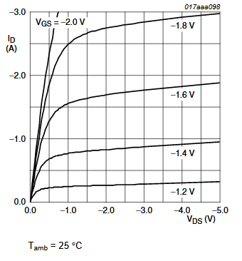
Through a “HIGH” on the input of the circuit, the BC547 will conduct and pull the gate of the p-FET down. The P-FET will open and allow voltage to be on the voltage divider. After the measurement, the input should be pulled “LOW” which will block any current to go through the voltage divider. As it is, the (3.3-0.6)/1000=2.4mA, ONLY when the pin is pulled HIGH. It is possible to increase the base resistor: the current going through the collector will be roughly 3.3/10.000=33uA. with an hFE of roughly 100, the current through the base would only need to be 0.33uA, so most likely a 68k base resistor would still be OK. The FET needs to be a type with a low RDSon and a Vgs of around -2-3 Volt (remember the Vgs(th) is when the Fet starts to conduct, still not up to full power). The values chosen for the resistors are pretty ‘safe’. Yet they also will consume power. It is possible to use a higher value. Make the 10k a 100k and you could make the 1k even a 1Mohm, provided the transistor has a decent hFE. The downside of using a 100k gate resistor is that the switch off time takes a bit longer (think ms). A suitable P-FET might be the NDX2301, that is a surface mount though. It has a Vgs of 1.8 Volt. It will not even need the transistor driver in front of it.
Another possibility is to give the sensors their own voltage regulator, that can be switched off by the ESP8266. The SPX3819 is a suitable one. Connect a GPIO pin to the ENABLE pin of the regulator. A HIGH (<= 0.25V) will switch it on, a LOW will switch it off. Make sure that the voltage regulator has a lower quiescent current than the peripherals you are switching with it (the SPX3819 has a quiescent current of 90uA, max 16V input, a voltage drop of 340mV and a max current of 800mA). Something similar can be done with the ME6211 (40uA quiescent current).
High-side switching can also be obtained by a PNP transistor, like so:
According to some older expressif documentation the status of the gpio pins is maintained in DeepSleep but can only drive 2uA. It is a bit unclear though in the updated version, saying the state of the pins on DeepSleep is no longer defined (table 1-1), though it seems to then contradict itself (page 5/9). When I measured myself. I always found the same status of my pins during deepsleep, regardless whether they were HIGH or LOW before deepsleep. Status was as follows:
D0 0V
D1 0V
D2 0V
D3 1V68
D4 3v3
D5 3v3
D6 3v3
D7 3v3
D8 3v3
Ofcourse from some pins this is to be expected (D0,D3,D4) but I had expected D8 (GPIO15) to be LOW.
The results teach us though that if you want to feed a sensor with HighSide switching through a a p-FET or PNP transistor, you’d better use pins D4-D7 to close it during deepsleep.
Some sensors –like the BME280– can be programmed to go to sleep in between measurements. For the BME280 this is the ‘Forced Mode’ if you then have a 1/min reading (Bosch calls this the ‘weather monitoring state’) the power consumption is 0.16uA. Using forced mode is also a good way to prevent/limit internal warming up of the chip, which would give skewed readings.
An ADC like the PCF8591 has a relatively low current use in ‘standbye’ as Vin equal to Vss or Vdd, which is not well possible in situ. (Chapter 14.1, Table 8).
The ubiquitous DHT11 has an operating current: 0.3mA (measuring) and 60uA (standby), as 60uA is still rather high, cutting off the power would be better. In that case however the DHT11 needs a 1 sec warming up period. The HTU21D is a better choice with a 0.14uA sleep current.
7. Do you need to send your values? Rather than sending every measurement when made, you could opt to store results in RTC/SPIFFS memory and only send them say once a day, or you could decide that if a new measurement result is say within 5% of the previous reading, there is no need to send it. If you are weary of RAM wear, you could add some FRAM, e.g. the MB85RS64V (8k, Operating current 1.5 mA. Standby current 10 μA) or MB85RC256V (32K, Operating current 200μA. Standby current 27uA) (library). (The 8k uses SPI, the 32k uses I2C).
8. Choose your batteries wisely Once you get to uA levels, self discharge of the batteries becomes an important competing factor. Nick Gammon states the following self discharge for a number of batteries:
Type
Capacity mAH
Discharge %/month
Self discharge (uA)
CR1212 (3V)
18
1
0.250
CR1620 (3V)
68
1
0.950
CR2032 (3V)
210
1
3
NiCD AAA (1.2V)
350
20
98
NiMH AAA (1.2V)
900
30
375
NiCd AA (1.2V)
1000
20
270
Alkaline AAA (1.5V)
1250
2
35
NiMH AA (1.2V)
2400
30
1000
Alkaline AA (1.5V)
2890
2
80
Li-Ion (3.7V)
4400
10
600
The LiFePO4 (Lithium Iron Phosphate) is worth considering as it’s max voltage is 3.6Volt and it’s nominal voltage 3.2Volt with a very flat discharge curve. One could opt to use these without a voltage regulator.
TIt is also possible to use a Lithium Thionyl Chloride battery without a voltage regulator. These batteries give 3.6 Volt…which is really at the top spec for the ESP8266. These non-rechargeable batteries generally have a very long life, with about 1% self-discharge per year. Keep in mind that in cold temperatures their internal resistance will increase significantly, so they need to be buffered when used in cold temperatures or your ESP8266 may crash when it needs power to connect to WiFi. You cannot do this with say 3×1.2 NiCd cells in series, as they may be well over 1.2 volt when fully charged and you could end up feeding 4,35 Volts to your ESP8266, which it really does not like. You could use a Lithium Thionyl Chloride battery with a voltage regulator, just to be safe, as long as you pick one with a voltage drop of less than 300mV
Further reduction of Power The Expressif documentation mentions 8 further ways to reduce power (chapter 4.5) that I have not tried myself and to be honest I have seen some back and forth on the various fora about it not working, about it being fixed and about it still not working.
Connecting D0/GPIO16 to RST In order for the wake up pulse to work, D0 needs to be connected to RST. The drawback of that is that you need to remove that link when you want to reflash the ESP8266. some people advise connecting the pins via a resistor. That has mixed results though. A better way is to use a Skottky diode -e.g a 1N5819– with the cathode to pin gpio16/D0 and the anode to the RST pin.
In a follow up article, I will publish some code that uses this deepsleep framework to read a sensor and send it to a database.
Part 1 -DeepSleep General Part 2 -DeepSleep HTTP publishing Part 3 -DeepSleep MQTT Publishing Part 4 -DeepSleep MQTT Subscribing Part 5 -Deepsleep ESP-NOW Part 6 – Power Down
Telegram is a ‘Whatsapp’ like app for mobile phones to exchange messages.
An advantage over Whatsapp or Viber is that it also allows you to communicate with your (micro)computer.
That means your phone can receive messages sent from your ESP8266 or ESP32, but also that your phone can be used to control your ESP8266 or ESP32.
In order to do so you need to have the telegram app installed, create your own bot to handle the traffic, get an API_key and the chat_id for your bot
Install Telegram
Visit Telegram official website and download the official application for your smartphone, or get it from the playstore
Create your Bot
Create your bot by using a bot called “BotFather”. To do this, add BotFather to your contacts or visit telegram.me/botfather and follow the instructions to create your own bot.
Get your API
When your bot is created, BotFather gives you the HTTP API token which follows a pattern like 123456789:AABBCCDD_abcdefghijklmnopqrstuvwxyz. You need this token to send messages.
Get your chat_id
You will need this ID to send messages, you do not need it to receive messages. Getting this ID is not straightforward and most of the methods i have seen on the internet do not work (anymore).
The only ones I found working is to the IDBot (and follow the instructions). and the get_id_bot. The latter can be a bit slow though. (I will mention a 3rd option further down)
Getting your chat ID with IDBotGetting your chat ID with get_id bot
The id is an integer and it follows a pattern like 123456789
Now it is time to test your bot.
You can do that with cURL
There is an other element that can be added at the end and that is &parse_mode=, but for normal operations we can leave that out or make it “&parse_mode=HTML”. A bit more on this further down
Using GET
So now we have our communication with Telegram working, we can go do something useful with it.
The fact that the API can be reached with a GET message opens up possibilities for an ESP8266, ESP32, Raspberry Pi or other controller that is connected to internet.
and the String url is the sum of the strings and variables you want to send
In your declaration section you would be stating:
WiFiClientSecure botclient;
The reason I am not putting a complete and ready “Telegram via GET” program here is because there is actually a pretty decent library program available, so if you insist on using your own GET statements rather than a library, I presume you do that to make very lean code in which case I presume you are versed enough in coding to build your own routine with the help of the above info.
If you use a GET URL to connect your ESP to Telegram and you are sure your code is correct, you may have a secure connection problem. Read On
Using a library
There are several libraries for Telegram available and you probably already find them in your library manager. The “UniversalTelegramBot” is a pretty decent one and the examples should get you up and running fast, even if from first glance it is not always clear what they do 🙂 .
So, install the library via library manager and lets have a look at the “PhotoFromURL”example.
When you fill in your WiFi credentials and Telegram API, you may wonder “where the heck goes my chat_id”.
Well, remember earlier I said you only needed the chat_id when you wanted to send something from yr micro to your phone? Well, that’s the case right here.
“Yes, but this program IS supposed to send me something and I clearly see a variable called chat_id, so where do I put mine” I hear you say.
Well this program will send you a picture ONLY when you tell it to do that and then the program will just read your chat_id from the incoming message and use that. This is also the 3rd method of finding your client ID
So here is what you do to use that example: After you upload it to your ESP8266, go to your Telegram app on your phone. select the bot you just created to send a message to and message /start.
After a few moments the bot responds with an overview of the commands you can give (only one in this case). Tap on that command to execute it.
It is not working If nothing happens, it is time to open the serial monitor.
You should see the IP number being printed. Make sure you type the correct command in your Telegram app and make sure you are sending it to the proper bot.
If you don’t see the ‘got response’ message appearing and you are sure you have inserted the right API, then apparently something else is keeping the program from opening a socket to the bot.
Could it be that you are still using the 2.5.0 ESP8266 core? There are plenty good reasons to use that core, but apparently it has a problem with secure connections. But not all is lost. Here is what you do:
Go to setup() and add
client.setInsecure();
and then compile and upload the file again.
Beware! In this example the WiFiSecure() client IS called client. That maybe different in other examples (in the Bulkmessages example it is called ‘secured_client’. Change your setInsecure statement accordingly.
Controlling your ESP8266/ESP32 via Telegram
It is possible to control your ESP via your Telegram App. In fact, that is what the previous example was already doing: we instructed it to send a photo.
The FlashLed example shows very clear how to control your ESP. If for testing you want to use the inbuild led from the Wemos, the ledPin should be ‘2’, the ledon routine should make the pin LOW and the ledoff routine should make the pin HIGH.
You could combine functions like so:
/******************************************************************* * How to use basic functiond of a Telegrambot * A completely changed example based on a sketch from * Vadim Sinitski *******************************************************************/#include <ESP8266WiFi.h>#include <WiFiClientSecure.h>#include <UniversalTelegramBot.h>// Initialize Wifi connection to the routercharssid[]="NETGEAR1";// your network SSID (name)charpassword[]="SECRET";// your network key// Initialize Telegram BOT#define BOTtoken "XXXXXXXXX:YYYYYYYYYYYYYYYYYYYYYYYYYYYYYYYYY" // your Bot Token (Get from Botfather)WiFiClientSecureclient;UniversalTelegramBotbot(BOTtoken,client);intBot_mtbs=1000;//mean time between scan messageslongBot_lasttime;//last time messages' scan has been doneboolStart=false;constintledPin=2;intledStatus=0;Stringtest_photo_url="https://img.srgcdn.com/e/w:750/cjh2NWp4S0FiNWxJQVNsQ3JUU28uanBn.jpg";// can insert any picture URLvoidhandleNewMessages(intnumNewMessages){Serial.println("handleNewMessages");Serial.println(String(numNewMessages));for(inti=0;i<numNewMessages;i++){Stringchat_id=String(bot.messages[i].chat_id);Stringtext=bot.messages[i].text;Stringfrom_name=bot.messages[i].from_name;if(from_name=="")from_name="Guest";if(text=="/get_photo"){bot.sendPhoto(chat_id,test_photo_url,"Who");}//-------------//add more commands here//-------------if(text=="/ledon"){digitalWrite(ledPin,LOW);// turn the LED on (HIGH is the voltage level)ledStatus=1;bot.sendMessage(chat_id,"Led is ON","");}if(text=="/ledoff"){ledStatus=0;digitalWrite(ledPin,HIGH);// turn the LED off (LOW is the voltage level)bot.sendMessage(chat_id,"Led is OFF","");}if(text=="/status"){if(ledStatus){bot.sendMessage(chat_id,"Led is ON","");}else{bot.sendMessage(chat_id,"Led is OFF","");}}if(text=="/start"){Stringwelcome="Welcome to Telegram Bot, "+from_name+".\n";welcome+="This will show several properies.\n\n";welcome+="/get_photo : getting photo\n";welcome+="/ledon : to switch the Led ON\n";welcome+="/ledoff : to switch the Led OFF\n";welcome+="/status : Returns current status of LED\n";bot.sendMessage(chat_id,welcome,"");}}}voidsetup(){Serial.begin(115200);// Set WiFi to station mode and disconnect from an AP if it was Previously connectedWiFi.mode(WIFI_STA);WiFi.disconnect();delay(100);// attempt to connect to Wifi network:Serial.print("Connecting Wifi: ");Serial.println(ssid);WiFi.begin(ssid,password);while(WiFi.status()!=WL_CONNECTED){Serial.print(".");delay(500);}Serial.println("");Serial.println("WiFi connected");Serial.print("IP address: ");Serial.println(WiFi.localIP());client.setInsecure();// if yr core cannot handle secure connectionspinMode(ledPin,OUTPUT);// initialize digital ledPin as an output.delay(10);digitalWrite(ledPin,HIGH);// initialize pin as off}voidloop(){if(millis()>Bot_lasttime+Bot_mtbs){intnumNewMessages=bot.getUpdates(bot.last_message_received+1);while(numNewMessages){Serial.println("got response");handleNewMessages(numNewMessages);numNewMessages=bot.getUpdates(bot.last_message_received+1);}Bot_lasttime=millis();}}
I just want to have my ESP send notifications
Well in fact the previous examples kinda did that, but if you really just want to have notifications sent to your phone from your ESP, then the only command you will need from the library is
bot.sendMessage(chat_id, "My message", "");
Provided of course you called your library object ‘bot’. Those empty quotes at the end are there for the parse_mode (read on).
Instead of “my message” you can also insert a String variable in which you add text and variables and you can even use simple HTML coding in that string. In that case the command needs to be:
bot.sendMessage(chat_id, messagestring, "HTML");
your messagestring could for instance be:
String messagestring="The temperature is <b>"+String(tempreading+ "</b>Celsius";