Timer Interrupts re-visited

Edit Jan 2022: Upon a review of this article, I noticed that WordPress had screwed up some of the command statements I had used, as it has some trouble using the greater and lesser than sign properly. This led to some text disappearing causing the code sometimes to become odd/unclear. It should be all OK now.

After I wrote an article on timer interrupts in the Arduino/AVR chips, I received some questions from people on how exactly to know what prescaler to use in setting timers and from some people who had problems reading the bitwise operators that are often being used, I will give some explanation here, but for a background on timers, I suggest you read my previous article on that subject:
Suppose you want your AVR to give an interrupt every second, then what is it you need to do?

Let’s first start with an AVR at 1MHz: (just as an example)
As 1MHz will create a timer interrupt every 1/1000.000 of a second, we would need to count 1.000.000 cycles to let a second pass. As the biggest timer is 16 bits, that can count to 65,535, that isn’t enough to count to 1,000,000. Therefore we have to divide the CPU frequency with a prescaler. But which one?
We can best chose that one as follows: If you look at all the prescalers (1 to 1024) you get the following table:
1,000,000 /1 = 1,000,000
1,000,000 / 8 = 125,000
1,000,000 / 64 = 15,625
1,000,000 / 256 = 3,906.25
1,000,000 / 1024 = 976.5625

We can already rule out 1 and 8 as prescaler because the resulting numbers are bigger than 16 bits (65,535).
We can also rule out 256 and 1024 because they result in a fraction and we cannot measure those and thus we would get an inaccuracy. Thus we are left with 64 as a prescaler. (I again emphasize this is for a 1MHz example, the Atmega 328 is 16 Mhz, we will get to that in a moment)

So what do we need to do to set up that prescaler. The datasheet ( “Timer/Counter1 Control Register B” (TCCR1B) Table 15-5) teaches us that we have to set bits CS10 and CS11 in the TCCR1B register.
cs-bits TCCR1B

There are various ways to set a bit in a register, but using a left shift is a very popular one:
We will do it as follows:

TCCR1B = 1<< CS11 | 1 <<CS10;

Ok so what does that mean? Well CS11 and CS10 are defined in io.h and are respectively on bit 1 and 0 in the timer register. CS11 and CS10 are therefore defined as “1” resp “0”. So if we substitute those values we will find:

1<<CS11| 1<<CS10;
1<<1 | 1<<0;
0b00000010 | 0b00000001;
0b00000011;

or to explain: a 0 left shift of 1 will give 0b00000001 and a 1 left shift of 1 will give 0b00000010.
If you then bitwise OR those values that looks like:
0b00000001
0b00000010
__________ OR
0b00000011

if you then do a bitwise OR of that number with the timer register, that gives
0bxxxxxxxx
0b00000011
__________ OR
0bxxxxxx11

How to assign values to the registers
Some care has to be taken in how you assign values  to the  various registers. If we have for instance the register TCCRB1, then on first instance we do not know what it’s register values are. So suppose they are 0bxxxxxxxx. If we then do TCCRB1= 1<<CS10;, TCCRB1 becomes 0b00000001;. That means ALL previous bits of the register have been erased and only bit 0 has been set. Normally we like preserving the previous bit states and only alter the one we are concerned with. We would do that with TCCRB1 |= 1<<CS10;.  The result would then be 0bxxxxxxx1.
The difference between  ‘|=’ and  ‘|’ is that the one is a compound OR and the other just an OR. With the compound OR we do not just do an OR, but then also  assign that value, in this case to TCCR1B.
Yet, with the TCCRB1 (and also The TCCRA1) register this is tricky , as  most of the bits in these registers serve some function  in what we are trying to do now. So suppose the register would have a content of 0b00000010; that we do not know about. If we decide that we like a prescaler of 256, so we need to set bit CS12. Now if we would  do that with TCCRB1 |=1<<CS12. But as we left the previous bits unaffected by using  a ‘compound OR’, the actual content  of the CS registers is  now 0b00000110;, which means there is no prescaler at all but the chip will be waiting for an external clock source and your program does not work.
That is why we use  the standard value assignment with ‘=’, so TCCRB1=1<<CS10;.
However, that also means that if we want to assign two registers, we have to be careful how we do that. Suppose you want to set both the CS10 and CS12 registers. The easiest then is to do that in one go: TCCRB1=1<<CS10 | 1<<CS12;.
If for reasons of say readability, you want to assign them separately, you have to do that like this:
TCCRB1 =1<<CS10;  (standard assignment).
TCCRB1 |=<<CS12; (Compound OR).

Counting cycles
As we picked a prescaler of 64 we  now we have to wait 1.000.000/64 =15,625 cycles to know that one second has passed (again, this is a 1MHz exaample, the 16Mhz Atmega328 is up next). How do we do that?
Well you could use a software counter in the interrupt routine that just counts to 15,625. That will work, but we can also use the hardware counter of Timer1. We do that by putting the timer in ‘Clear Timer on Compare Match’ mode or CTC mode. In this mode the Timer will compare itself with a set value and trigger an interrupt when it reaches that value.

We store that value in the OCR1A register. That is a 16 bits register
ocr1a
In this case we can just do:
OCR1A=15624
We set that 1 less than the value we found, because microcontrollers start counting at 0 and not 1
A bitwise OR is not necessary because the entire register is reserved for the compare value.
We also will have to set the CTC mode. To set the proper bits for that we consult table 15-4, that describes the Waveform generation mode.
wgm
Obviously we need to choose Mode 4 because we want to use the value in OCR1A. The tabel shows we have to set the WGM12 bit

We do that with the following statement:
TCCR1B = 1<<WGM12
as WGM12 is defined as ‘3’
What we do is: TCCR1B =1<<3
This is 0b00001000
OR-ed withTCCR1B gives:

xxxxxx11
00001000
________OR
xxxx1x11

We are not done yet. We have now set up the timer to generate 1 sec interrupts, but we need to start the timer.
we do that with the TIMSK1 register. The datasheet tells us that we have to set the ‘Output Compare Match Interrupt Enable bit for timer 1 (OCIE1A).
We do that as follows:
TIMSK1 =1<<OCIE1A;
as OCIE1A is defined as ‘1’, you can again do the math:
TIMSK1 = 0b00000010 i.e. bit 1 will be set

So the entire code in the setup now will be: (NB: This is an example for if we would have an 1MHz Atmega)

cli(); //Disable global interrupts
TCCR1B = ((1<< CS11) | (1<< CS10));
OCR1A = 15624; //Count 15625 cycles for 1 second interrupt
TCCR1B |= 1<<WGM12; //Put Timer/Counter1 in CTC mode
TIMSK1 = 1<<OCIE1A; //enable timer compare interrupt
sei(); //Enable global interrupts


Two statements I have not discussed yet, the cli() (clear/disable global interrupts) and sei() (set/enable global interrupts). We use those statements because we are setting up the interrupt, so just to make sure that that isn’t interrupted by a still active interrupt, we temporarily stop all interrupts and at the end enable them again..

Now for a 16 Mhz Atmega328
OK, we now know how to set it up for 1 MHz… but most arduinos do 16 MHz.
Well, that is basically the same:
16,000,000 / 1 = 16,000,000
16,000,000 / 8 = 2,000,000
16,000,000 / 64 = 25,000
16,000,000 / 256 = 62,500
16,000,000 / 1024 = 15,625
Here we could actually choose 2 prescalers: 256 or 1024.
table 15-5 teaches us that involves setting bits CS12 for 256 or CS12 and CS10 for 1024.
That would be done with the statements:

TCCR1B = 1<<WGM12 | 0b01<<CS12;
OCR1A = 62499; //Count 62499 cycles for 1 second interrupt
or
TCCR1B = 1<<WGM12 | 0b01 <<CS10 | 0b01<<CS12;
OCR1A = 15624; //Count 15624 cycles for 1 second interrupt

There are other ways of setting timers such as pre-loading, but for that better read my earlier article on timer interrupts
Just a word of warning: Another way of changing the frequency is done by setting fuses. The Atmega328 for example is often used with a 16 MHz crystal, but it can also be used with its internal 8MHz oscillator, additionally it already can be set to have its internal clock divided by 8, causing the CPU to go at 1 MHz and not 8 or 16.

A practical example
In my earlier article on Timer Interrupts, I gave a practicle example of a flashing LED, still using “digitalWrite()” for that.
As we are using a lot of registers for the timer, why not go into using Registers for the LED function as well:
There are three registers for each pin that that are important for us: Data Direction Register (DDR), Port register (PORT) and Pin register (PIN). Each of these will be suffixed with a letter corresponding to which set of pins we are working with. If the LED is connected to pin D13, that means it is connected to Port B bit 5 so we need to work with DDRB, PORTB, and if we was using inputs, PINB.

//Setup the I/O for the LED
DDRB |= (1<<5); //Set PortB Pin5 as an output
PORTB |= (1<<5); //Set PortB Pin5 high to turn on LED

Handling the interrupt
We have now set up everything: an interrupt will be generated every second, but we still have to tel the Arduino what to do with the interrupt. We do that in an Interrupt Service Routine (ISR). The rest of the code is halted and this routine is run. It is best to keep interrupt routines as short as possible: not a problem in this case as we just need to toggle the LED:

ISR(TIMER1_COMPA_vect) //Interrupt Service Routine
{
PORTB ^= (1<<5); //Use xor to toggle the LED
}

The name of the interrupt routine is not random: The datasheet defines the interrupt source for Timer/Counter1 Compare A match as “TIMER1 COMPA”. We use that name while replacing spaces with underscores and adding a lower case “vect” at the end. This is how the compiler knows which ISR belongs to different interrupt sources. We toggle the LED with the XOR operator and a bitmask. The bitmask ensures that only bit 5 will be changed. The XOR is a function that renders ‘0’  for bits that are the same and ‘1’ for bits that are different.
That goes as follows:
1<<5
suppose at a certain moment Port B = 0b00100000 (LED on)

0b00100000
0b00100000
__________ XOR
0b00000000
(=LED OFF)
and at the next interrupt:

0b00000000
0b00100000
__________ XOR
0b00100000
(=LED ON)

The entire code will thus be:

void setup() {
  cli();
  TCCR1A = 0b01 << COM1B0 | 0b00 << WGM10 ;
  TCCR1B = 1 << WGM12 | 0b101 << CS10;
  OCR1A = 15624; // count 15625 cycles for 1 second
  //Put timer Counter in CTC mode
  TIMSK1 = 1 << OCIE1A; //Enable timer compare interrupt
  sei();// Enable Global interrupt //-----------------------
  DDRB |= (1 << 5); //Set PortB Pin5 as an output
}
void loop()
{
//other code
}

ISR(TIMER1_COMPA_vect) //Interrupt Service Routine
{
  PORTB ^= (1 << 5); //Use xor to toggle the LED
//PORTB = PORTB ^ B00100000;//as above, leaving the other bits intact
  
}

As website can easily screw up computer codes, here is a screenshot of what it should look like:
blink-timer

Let’s quickly walk through that code again:
cli();
Stops the interrupts, just to make sure the setup isn’t disturbed.

TCCR1A=0b01<<COM1B0;
tccr1a-b

Actually you do not need this statement, the program will be fine without it. I included it for the following reason: When it is set, the OC1B output overrides the normal port functionality of the I/O pin it is connected to. OK, what pin is it ‘connected to’?

oc1b

It is connected to PB2 which is digital I/O pin 10 on the UNO. That means that if we would have chosen D10 to flash the LED rather than D13, we would not have needed any code in the interrupt vector to flash an LED but just let the hardware timer do its work directly. The entire code would then have been only 4 lines:

void setup() {
  DDRB = DDRB | 1<<DDB2;               // Make D10 (PB2) an output
  TCCR1A = 0b01<<COM1B0 | 0b00<<WGM10; // Toggle OC1B on match, CTC mode
  TCCR1B = 0b01<<WGM12 | 0b101<<CS10;   // CTC mode, prescaler 1024
  OCR1A = 15624;                       // number of cycles 15625
}

One can do something similar with D9 that is connected to OC1A and D11 that is connected to OC2A.

TCR1B=0b01 <<WGM12;
Puts a ‘1’ in the WGM12 register, choosing CTC mode
wgm10-4

TCCR1B = 0b01 << WGM12 | 0b101 << CS10;
This is a short way of putting a 1 in both the CS10 as well as the CS12 register of TCCR1B, choosing a prescaler of 1024.
cs-bits-1

OCR1A = 15624;
This sets the amount of cycles that needs to be counted minus 1 (since microcontrollers start counting at 0).

TIMSK1 = 1<<OCIE1A;
This sets bit 1 of the Timer/counter interrupt mask register. Bit 1 is called OCIEA which is the “Output Compare A Match Interrupt Enable” It enables the TIMER1 COMPA interrupt.

timsk

sei();
This  enables all the interrupts again that were previously silenced with cli();

DDRB |= (1 << 5); //Set PortB Pin5 as an output
It puts a ‘1’ in bit 5 of the datadirection register. bit 5 corresponds with digital pin 13, so in fact this is a quick way of writing “pinMode(13,OUTPUT);” As I am using a compound OR statement (|=), the status of any other pin remains unchanged.

ddrb

PORTB ^= (1 << 5);
This toggles bit 5 of the PORTB register, which is akin to pin D13. In fact it says: digitalWrite(13,HIGH); if  D13 was ‘LOW’ and digitalWrite(13,LOW); if pin D13 was previously HIGH.

Should you change the code into only making CS12 HIGH rather than CS12 and CS10 (i.e. prescaler=256) and  make the OCR1A into (16.000.000/256)-1=62500-1=62499, that the code works as well.

Some handy website are here:
Fuse calculator
Bitwise calculator
Timer calculator
Installing Attiny13 core files in Arduino IDE 1.6.x and 1.7.x

Note! Currently I suggest you follow the instructions here, to install via the boardmanager

The installation for the Attiny13 in the Arduino IDE 1.0x was  fairly straightforward and is described in my ibble.
The Arduino IDE from Version 1.6  and newer, have a different structure for choosing the processor-board: Under ‘Tools’ you have to seperately choose the board, the processor and the speed. If you have installed the MIT cores for attiny 44-84 and 45-85, under ‘Tools-Board’ you will see a seperate class for  ‘Attiny’ processors, while under ‘Tools-Processors’ you will be able to choose for an  attiny85/45 or attiny44/84. You will however no longer see your attiny13 core there.

In order to be able to select the attiny13 again you need to put it in the new file structure.
I will describe that for the Smeezekitty core.

First, close your IDE, as any changes will need a restart anyway.
Download the Smeezekitty core. You will get a file called Core13-20.zip that contains 15 files but no boards.txt file.

Open your explorer and go to your hardware folder, that is located in your sketches folder. In the hardware folder you should see  the folder ‘attiny'(if you have the MIT attiny core installed). If it doesn’t exist, create it. If you open the attiny folder you will see a folder called “avr” open that one. If it doesn’t exist, create the folder “avr”. When you open it, you will see a  folder ‘variants’ and the “boards.txt” file. If they do not exist, create them.
open the folder variants. You probably will see 2 folders called “tiny8” and “tiny14”. Create a folder called ‘Core13’
Open  the downloaded Smeezekitty core and put the  15 files directly in the ‘Core13’ folder. Not in a subfolder

If you already have the smeezekitty core installed for the  Arduino IDE 1.0x  then copy that folder – that is likely called ‘core13’- in the ‘variants’ folder.

Go back to the  ../hardware/attiny/avr/ folder and make a copy of the boards.txt, then open the boards.txt and add the following lines at the bottom:
#################################################
attiny.menu.cpu.attiny13=ATtiny13
attiny.menu.cpu.attiny13.upload.maximum_size=1024
attiny.menu.cpu.attiny13.build.mcu=attiny13
attiny.menu.cpu.attiny13.build.variant=core13

attiny.menu.clock.internal96=9.6MHz (internal)
attiny.menu.clock.internal96.bootloader.low_fuses=0x7A
attiny.menu.clock.internal96.bootloader.high_fuses=0xff
attiny.menu.clock.internal96.build.f_cpu=9600000L
################################################

attiny.menu.clock.internal48=4.8MHz (internal)
attiny.menu.clock.internal48.bootloader.low_fuses=0x79
attiny.menu.clock.internal48.bootloader.high_fuses=0xff
attiny.menu.clock.internal48.build.f_cpu=4800000L
################################################

If you had to create your boards.txt file yourself Then make sure you add at the top the following lines:
##############################################
menu.cpu=Processor
menu.clock=Clock

attiny.name=ATtiny
attiny.bootloader.tool=arduino:avrdude
attiny.bootloader.unlock_bits=0xff
attiny.bootloader.lock_bits=0xff
attiny.build.core=arduino:arduino
attiny.build.board=attiny
attiny.upload.tool=arduino:avrdude
##############################################

save the boards.txt file and start your Arduino IDE 1.6.x or 1.7.x. Go to Tools-Board and select ‘Attiny’. Then go to ‘Tools-Processor’ and check if the Attiny13 is present. Go to ‘Tools-Clock’ and check for 4.8 MHz and 9.6MHz (internal).

Anyway, just to make sure you have the right folder stucture: this is what you should have:
…/hardware/attiny/avr/variants/core13/(some 15 files)
…/hardware/attiny/avr/boards.txt

NOTE: If on burning the bootloader to set the proper fuses you get an ‘efuse’ error, that is because teh boards.txt defines the root core as “Arduino” that might be fine for the 25/45/85 series as they have an extended fuse. But the Attiny13 has not. Changing it in the  ‘variants’ section apparently is not enough. You then have to give the attiny13 its own menu section. You do that like this:
###############################
menu.cpu=Processor
menu.clock=Clock

attiny13.name=Attiny13
attiny13.bootloader.tool=arduino:avrdude
attiny13.bootloader.unlock_bits=0xff
attiny13.bootloader.lock_bits=0xff
attiny13.build.core=arduino:core13
attiny13.build.board=attiny
attiny13.upload.tool=arduino:arduinoisp

#########################

attiny.name=ATtiny45/85
attiny.bootloader.tool=arduino:avrdude
attiny.bootloader.unlock_bits=0xff
attiny.bootloader.lock_bits=0xff
attiny.build.core=arduino:arduino
attiny.build.board=attiny
attiny.upload.tool=arduino:avrdude

attiny.menu.cpu.attiny45=ATtiny45
attiny.menu.cpu.attiny45.upload.maximum_size=4096
attiny.menu.cpu.attiny45.build.mcu=attiny45
attiny.menu.cpu.attiny45.build.variant=tiny8

attiny.menu.cpu.attiny85=ATtiny85
attiny.menu.cpu.attiny85.upload.maximum_size=8192
attiny.menu.cpu.attiny85.build.mcu=attiny85
attiny.menu.cpu.attiny85.build.variant=tiny8

attiny.menu.cpu.attiny44=ATtiny44
attiny.menu.cpu.attiny44.upload.maximum_size=4096
attiny.menu.cpu.attiny44.build.mcu=attiny44
attiny.menu.cpu.attiny44.build.variant=tiny14

attiny.menu.cpu.attiny84=ATtiny84
attiny.menu.cpu.attiny84.upload.maximum_size=8192
attiny.menu.cpu.attiny84.build.mcu=attiny84
attiny.menu.cpu.attiny84.build.variant=tiny14

attiny.menu.clock.internal1=1 MHz (internal)
attiny.menu.clock.internal1.bootloader.low_fuses=0x62
attiny.menu.clock.internal1.bootloader.high_fuses=0xdf
attiny.menu.clock.internal1.bootloader.extended_fuses=0xff
attiny.menu.clock.internal1.build.f_cpu=1000000L

attiny.menu.clock.internal8=8 MHz (internal)
attiny.menu.clock.internal8.bootloader.low_fuses=0xe2
attiny.menu.clock.internal8.bootloader.high_fuses=0xdf
attiny.menu.clock.internal8.bootloader.extended_fuses=0xff
attiny.menu.clock.internal8.build.f_cpu=8000000L

attiny.menu.clock.external8=8 MHz (external)
attiny.menu.clock.external8.bootloader.low_fuses=0xfe
attiny.menu.clock.external8.bootloader.high_fuses=0xdf
attiny.menu.clock.external8.bootloader.extended_fuses=0xff
attiny.menu.clock.external8.build.f_cpu=8000000L

attiny.menu.clock.external16=16 MHz (external)
attiny.menu.clock.external16.bootloader.low_fuses=0xfe
attiny.menu.clock.external16.bootloader.high_fuses=0xdf
attiny.menu.clock.external16.bootloader.extended_fuses=0xff
attiny.menu.clock.external16.build.f_cpu=16000000L

attiny.menu.clock.external20=20 MHz (external)
attiny.menu.clock.external20.bootloader.low_fuses=0xfe
attiny.menu.clock.external20.bootloader.high_fuses=0xdf
attiny.menu.clock.external20.bootloader.extended_fuses=0xff
attiny.menu.clock.external20.build.f_cpu=20000000L

#################################################
attiny13.menu.cpu.attiny13=ATtiny13
attiny13.menu.cpu.attiny13.upload.maximum_size=1024
attiny13.menu.cpu.attiny13.build.mcu=attiny13
attiny13.menu.cpu.attiny13.build.variant=core13

attiny13.menu.clock.internal48=4.8MHz (internal)
attiny13.menu.clock.internal48.bootloader.low_fuses=0x7A
attiny13.menu.clock.internal48.bootloader.high_fuses=0xff
attiny13.menu.clock.internal48.build.f_cpu=4800000L

attiny13.menu.clock.internal96=9.6MHz (internal)
attiny13.menu.clock.internal96.bootloader.low_fuses=0x79
attiny13.menu.clock.internal96.bootloader.high_fuses=0xff
attiny13.menu.clock.internal96.build.f_cpu=9600000L

################################################
attiny.menu.cpu.attiny2313=Attiny2313
attiny.menu.cpu.attiny2313.upload.maximum_size=2048
attiny.menu.cpu.attiny2313.build.mcu=attiny2313
attiny.menu.cpu.attiny2313.build.variant=attiny2313

attiny.menu.clock.internal8=8 MHz (internal)
attiny.menu.clock.internal8.bootloader.low_fuses=0xE4
attiny.menu.clock.internal8.bootloader.high_fuses=0xDF
attiny.menu.clock.internal8.bootloader.extended_fuses=0xFF
attiny.menu.clock.internal8.build.f_cpu=8000000L

Everything should be ok now but if you experience problems with delay and mills functions, you may still have an old Arduinocore. Check the code in hardware/arduino/cores/arduino/wiring.c, and find this section:

#if defined(__AVR_ATtiny24__) || defined(__AVR_ATtiny44__) || defined(__AVR_ATtiny84__)
SIGNAL(TIM0_OVF_vect)
#else
SIGNAL(TIMER0_OVF_vect)
#endif

The header file for the attiny13 (iotn13.h) shows the interrupt macro for timer overflow for attiny13 to be TIM0_OVF_vect and not TIMER0_OVF_vect. The fix is adding an additional OR condition:

#if defined(__AVR_ATtiny24__) || defined(__AVR_ATtiny44__) || defined(__AVR_ATtiny84__) || (__AVR_ATtiny13__)
SIGNAL(TIM0_OVF_vect)
#else
SIGNAL(TIMER0_OVF_vect)
#endif

Sending sensor data wireless (433MHz) with an Attiny85 or Attiny45 with Manchestercode

P1060016
instructables-transmitter

In an earlier article I described how to send RF/wireless data between two Attiny85 chips with a 433 MHz transmitter/Receiver pair.
Now I will  give a more practical program that sends  3 variables from an LDR and a DHT11 sensor.
The connections are simple
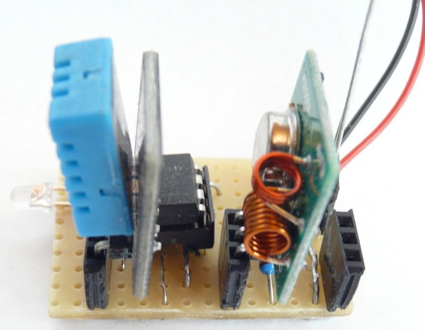
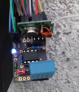
The transmitter is connected to D0 (pin 5). The DHT11 sensor is connected to D4 (pin 3) and an LDR connected to A1 (pin 7), with the other end connected to Vcc and a corresponding pull down resistor.
The big photo shows a test circuit on stripboard, The smaller picture shows the final PCB. The huge amount of  cables at the top doesn’t mean much, I just use a few

/*
Pin 2 =A3 D3
pin 3 = A2 D4
pin5 =D0
Pin 6=D1
Pin7= D2 A1

LDR=A1
PIR= D1
RF433=D0
DHT11=D4
LED=D3
*/
// libraries
#include <dht11.h> //Rob Tillaert
#include <Manchester.h>
dht11 DHT11;
#define DHT11PIN 4
#define TX_PIN 0  //pin where your transmitter is connected
//variables
float h=0;
float t=0;
int transmit_data = 2761;
int transmit_t = 0; // temperature
int transmit_h = 0; // humidity
int transmit_l=0; // lightlevel
int transmit_p = 0; //PIR
int transmit_s = 0; /Station identifier
byte ledPin=3;
int light=0;

void setup() {
pinMode(1, INPUT);
pinMode(ledPin,OUTPUT);
man.setupTransmit(TX_PIN, MAN_1200);
}

void loop() {
int chk = DHT11.read(DHT11PIN);
h=DHT11.humidity;
t=DHT11.temperature;
transmit_h=2000+h;
transmit_t=2100+t;
transmit_l=2200+(analogRead(A1)/10);
transmit_p=2300+digitalRead(1);
transmit_s=2500;
digitalWrite(ledPin,HIGH);
man.transmit(transmit_h);
delay(200);
man.transmit(transmit_t);
delay(200);
man.transmit(transmit_l);
delay(200);
digitalWrite(ledPin,LOW);
delay(1000);
}

The idea of adding a number, in this case in the 2000 range is to be able to identify what (which station) is sending the data: any 2000 number I know is humidity, any 2100 number I know is temperature, etc. Variables h and t are floats that can have decimals. As I am only interested in 2 digit accuracy, I just add them to an integer and thus turn them into integers. WIth regard to the lightlevel as it is an analog read it might be as high as 1023 (theoretically), so when it is divided by 10, the range will usuallu be 99 max a two digit number. If by any chance it would be 100, the transmitter will send a number as 24xx. The receiving software then knows it is a more than 2 digit value, but that will be very rare I then send 5  values: Humidity, temperature, light PIR and a station identifier ending the data. The receiving station then can identify where it came from and process the incoming signals (starting by dividing subtracting  the first two digits).
WIth regard to the lightlevel as it is an analog read it might be as high as 1023 (theoretically), so when it is divided by 10, the range will usually be 99 max a two digit number. If by any chance it would be 100, the transmitter will send a number as 24xx. The receiving software then knows it is a more than 2 digit value, but that will be very rare

It takes 3374 bytes so I could compile it in an Attiny45.

See also: DHT11 on Attiny85
Attiny DHT 11 & 433 MHz (with Oregon code)

analogRead() on Attiny13

I had an Attiny85 in a circuit performing functions that I thought could also be done by the smaller Attiny13, so I programmed the attiny13 with the same code as the attiny85, swapped both chips, tested my circuit and nothing happened……..
Flipped the attiny85 back in, worked correct, put the attiny13 in, didnt work.
Basically what the circuit does is to read two analog values, compare these and switch an output depending on the values read.
I stripped out all the functions to get to the bare necessity of reading only one analog port… what could be wrong with that? but still it didnt work.
Though debugging is a bit difficult with an attiny13 -you sort of have to guess whats going on- but I suspected the analogRead to somehow hang.
As I am using the ‘smeezekitty’ core and smeezekitty states that  that could happen with an older core, I made sure I had an update, but again the same problem..
Anyway, after long searches i fugured i had to add the “analogReference(0)” statement in the setup and indeed that worked.
So the setup of my program became:

void setup()
{
#ifdef __AVR_ATtiny13__
analogReference(0);//this line is essential for the Attiny13
#endif
}

ofcourse you could leave out the conditional parameters but this way the code is suitable for the 13 and for the 25/45/85 series

Slow ‘Tools’ menu in Arduino IDE

On a windows machine, the  Arduino IDE can sometimes be rather slow in opening and  can take up to 30 seconds before the ‘Tools’ Menu will open. Supposedly this is due to the fact that a port-scan is made, where especially if bluetooth dongles are used, Windows may wait long for a time out.
The problem and a solution are described here. (Road to solve the delay on the Arduino IDE.)
The solution is to replace the rxtxSerial.dll.

Using Attiny with RCSwitch and RemoteSwitch

It is possible to use the RCSwitch library in combination with an Attiny85 in order to send data.

/* 
Example for different sending methods
http://code.google.com/p/rc-switch/ 
*/ 
#include <rcswitch.h>
RCSwitch mySwitch = RCSwitch();
 
void setup() {
   // Transmitter is connected to Attiny Pin PB3  <--
   // That is physical pin2
  mySwitch.enableTransmit(3);
 
  // Optional set pulse length.
  // mySwitch.setPulseLength(320);
  // Optional set protocol (default is 1, will work for most outlets)
  // mySwitch.setProtocol(2);
  // Optional set number of transmission repetitions.
  // mySwitch.setRepeatTransmit(15);
}
 
void loop() {
  /* See Example: TypeA_WithDIPSwitches */
  mySwitch.switchOn("10101", "10000");
  delay(1000);
  mySwitch.switchOff("10101", "10000");
  delay(2000);
 }

The sketch uses 4754 bytes of program memory (has 8k) and 203 bytes (has 512 bytes) of SRAM. Receiving data  with an Attiny85, using the RCSwitch library is NOT possible as the receiver functions have been explicitly #define’d out for the Attiny

The other main 433MHz library, the RemoteSwitch library, does not compile for the Attiny because even when transmitting, a call is made to the receiver library, that has SerialPrint routines. These will not compile for the Attiny85. However, the modification of the RemoteSwitch library made by Jeroen Meijer, does compile on, and works with the Attiny 85 and 45. (No longer on GitHub but here)

/*
Switches the 3 devices from the Elro AB440
and 3 devices of the SelectRemote1728029
*/
#include <RemoteSwitch.h>
// declaration of the Elro AB440 creator
ElroAb440Switch ab440Switch(3);
//declaration of the SelectRemote creator
BlokkerSwitch3 blokkerTransmitter(7);
void setup() {
}
void loop() {
//Switch on SelectRemote 1728029 device 1
blokkerTransmitter.sendSignal(1,true);
blokkerTransmitter.sendSignal(2,true);
blokkerTransmitter.sendSignal(3,true);
//Switch on AB440-device B on system code 29.
//dip switch 1-5 is on-off-on-on-on = 10111... but is read as 11101='29'
ab440Switch.sendSignal(29,'A',true);
ab440Switch.sendSignal(29,'B',true);
ab440Switch.sendSignal(29,'C',true);
delay(2000);
blokkerTransmitter.sendSignal(1,false);
blokkerTransmitter.sendSignal(2,false);
blokkerTransmitter.sendSignal(3,false);
ab440Switch.sendSignal(29,'A',false);
ab440Switch.sendSignal(29,'B',false);
ab440Switch.sendSignal(29,'C',false);
delay(2000);
}

This program compiles in 2622k of program memory and 61 bytes of dynamic memory