Gardeners who use a resistive moisture sensor to measure the moisture of the soil, sooner or later get faced with corrosion of their metal sensor. Though practically all metals corrode in the soil, in this case it is sped up by the fact that a current flows through the sensor, causing electrolysis.
Several solutions are suggested to solve that like: ‘you have to feed them with AC’ but those solutions are not always practical.
There is however a fairly simple method to minimize the electrolysis and that is to switch off current through the sensor when you do not need it.
Moist soils do not need constant measuring, maybe 3-4 times a day is enough, so if you switch off the sensor except for the say 3x a milisecond or so that makes a big difference.
Easiest might be to use an I/O pin to feed the sensor, but not everybody feels comfortable doing that and not all microcontrollers are suitable for that (although the arduino probably is with 40mA per pin).
But it is in fact quite easy to use a transistor -controlled by an I/O pin- to switch the sensor on and off. Figure 1 gives an example of how to do that with either low side switching or high side switching.
 Figure 1a is a very basic transistor switch: Pull the base of the transistor HIGH and current will flow through the sensor, pull it LOW and the current will be switched off. Remember there will be a slight voltage drop (say 250-450 mVolt) over the transistor.
Fig 1b is also a rather basic transistor configuration, it is the emitter-follower or common collector that is often used in voltage buffering. Here also a LOW on the base will switch the transistor OFF and a HIGH will switch it on. Also here one has to take a voltage drop into account (basically the voltage on the I/O pin minus 0.6 Volt). Mind you that Fig 1&2 just give a basic circuit. You’ll need to add a base resistor and possibly a pull-down or pull-up resistor, depending on what state you want the circuit to start in.
 Figure 2 shows two other circuits you may be considering to try, but that’s not necessarily a good idea.
Fig 2A is basically identical to Fig 1A, but with the sensor and series resistor switched position in the voltage divider.
That does not work because even when the transistor is switched off, there still could be a current flowing through the sensor via the internal impedance of the microcontroller input.
Figure 2B shows a PNP transistor used. That should work right? After all it is basically figure 1A but then reversed in polarity. Well, it is not that simple. The I/O pin is tied to a microcontroller running at say 5V, so its voltage level will vary between 0 and a bit less than 5 Volt. At best it might be 4.2 Volt.*
To keep the PNP transistor switched off, we need to keep the base voltage at nearly the same level as that “+” line and that is hard in this configuration. Therefore opening the transistor is not a problem, but closing it might, although it will ‘probably’ work
Mind you that Fig 1 and 2 just give a basic circuit. You’ll need to add a base resistor and possibly a pull-down or pull-up resistor, depending on what state you want the circuit to start in.
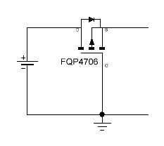
*A pFET on the other hand is quite suitable for high side switching