
Month: December 2012
Electret microphone amplifier

Amplifier for an electret microphone that can be used to detect sound with an Arduino or other microcontroller. The op-amp used is a TLC272 that is pin compatible with a number of other dual op-amps such as the LM393 the LM358 or the OPA2344 and OPA2345.
IC1a is used as a non-inverting amplifier. It offers a higher impedance as the inverting amplifier. The gain of the non-inverting amplifier is determined by 1+R4/R1 and is 40dB (100x). If desired a trim pot can be used for R4.
In most cases it is possible to DC couple the circuit. However in this case it is necessary to ensure that the non-inverting has a DC path to earth for the very small input current that is needed. This can be achieved by resistor, R2 in the diagram. The value of this may typically be 100 kOhms or more. If this resistor is not inserted the output of the operational amplifier will be driven into one of the voltage rails.
When adding a resistor in this manner the capacitor-resistor combination forms a high pass filter with a cut-off frequency. The cut off point occurs at a frequency where the capacitive reactance is equal to the resistance. This is expressed in the Formula 1/2πRC. For the used combination it is =16Hz.
The output on pin 1 is at best a sinus wave and though microcontrollers do not really like those or any other odd shaped wave, when fed to their ADC input that does not make a difference. However, if the output of IC1a is fed to an ADC there will be very strong fluctuations in the reading and as such the signal is not really representing the total sound pressure. We do that with op-amp IC1b that is used as a comparator with a reference voltage on the inverting entrance. When fed with 5Volt, the Voltage on the inverting entrance will be 72mV ((5000/69)*1)
As long as V- < V+, Vo will be low, but when the sound level rises above 72mV, IC1b will make the output go high.
With a gain of 100 in IC1a, a voltage off 720uV from the microphone would be enough. The Voltage build up over C3 is depending on the number of times the Output goes high and thus is an indication for the sound pressure.

The PCB is quite simple. The convoluted area above the double op-amp is to either insert a resistor, or an upright trim pot that can be inserted facing, or facing away from the IC.
There are 4 extra components in comparison with the circuit. Those are 2 LED’s and 2 resistors. These give an indication of the Output voltage as well as the supply voltage. They are optional however:

There are many commercially available electret breakout boards for the Arduino (or other micro controllers). One of them is the Sparkfun breakout board:
 Sparkfun had a bit of a rocky start in this area with their BOB-08669 and they replaced it with the BOB-09964, the difference between the two being some changes in resistor and capacitor values.
The Sparkfun board is centered around 1 op-amp, the OPA344 that is used as an inverting amplifier. The gain is determined by R5/R4 and is 40dB (100x). The input high pass RC filter cuts off frequencies below 10Hz. The RC network with C3 and R5 cut off above 13 kHz. The original BOB-08669 would cut off too high and it’s impedance was too low (as can be expected from an inverting op amp). The cut-off for the low pass filter can be calculated from xc=1/2πRC, in which xc being the reactive capacitance. With the given values of 12pF and 1Mhz the low pass is determined at 13.2kHz. The high pass around C1 and R4 gives a cut off of 3.3Hz (so not 10Hz as stated).
R2 and R3 give an off-set adjustment centered around half voltage (2.5 Volts).
Though the new board is an improvement over the old one, still a lot of people experienced problems with it. It did not really change in design, just a few R and C values were adapted.
Dealextreme offers a board based around a 393. It has an audio out and a digital out for if the signal comes above a certain threshold. It is the KY-037 from Keyes and has a 12 turn potentiometer to set the threshold. It is rumoured to have low sensitivity.
Freetronics board
The Freetronics board is also based upon the TLC272. It offers an audio output and a sound pressure output with visual indication. Here the peak detection on pin 6 of the IC is set to 71 mV and the gain of the first opamp is set to 100

Using a Single Opamp

Using a single op-amp of course is also possible and this time we will use the inverting pin of an LM741. The gain = R4/R3 =1000=60dB.
D1 and D2 form a voltage doubler, rectifier and peak detector.
C3 and R5 form an RC delay for the analog entrance of the Arduino
Using the LM386
Although the LM386 is primarily aimed to drive a speaker, it can be used as a microphone pre-amp. results with it however have been less than satisfying.
Using the LM358
The LM358 gives better results than the LM386.
Testing
The following code can be used to easily test the workings of the amplifier in combination with an Arduuino. The code reads the input 10.000 tmes and then prints the min, the max and the spread
/**
 * Measures the voltage on an analog pin over a ~1s period
 * of time and sends the Min, Max and Diff (Spread) values
 * over Serial.
 *
 * Author:
 * Dimitar Kovachev, http://lowvoltage.wordpress.com/
 *
 */
const int analogPin = 0;

void setup() {
  Serial.begin(9600);
}

void loop() {
  int mn = 1024;     // mn only decreases
  int mx = 0;        // mx only increases

  // Perform 10000 reads. Update mn and mx for each one.
  for (int i = 0; i < 10000; ++i) {
    int val = analogRead(analogPin);
    mn = min(mn, val);
    mx = max(mx, val);
  }

  // Send min, max and delta over Serial
  Serial.print("m=");
  Serial.print(mn);
  Serial.print(" M=");
  Serial.print(mx);
  Serial.print(" D=");
  Serial.print(mx-mn);
  Serial.println();
}
Cheap PIR hack
 I picked up a motion sensitive nightlight at a thrift store. It runs on 3 AA batteries and lights up 3 pretty bright LED’s if an object approaches the sensor. The one I have goes under different names sysch as the YL-253 (YL stands for Yilin). In the Netherlands it is sold at the ACTION shops for 2.59 euro
As it goes through its batteries pretty fast and one of the dead cells had leaked in the battery comportment, I wondered if I could perhaps use it as a motion sensor for my Arduino.
The case opens with 4 screws and then reveals a circuit board with an LP0001 chip on it and a big fat photosensitive element that probably is a PIS209S or a D203s. The D, S and G of this sensor do not stand for Drain.Source and Gate, but for Drain, Source and Ground. The signal is picked up from the Source. It is a Dual Element detector with an openings angle of 120 degrees. It operates between 3 and 15 Volts and has a load resistance of 47k.
The DIL16 chip is an LP0001. That is a PIR (passive infra-red controller) and supposedly one of the most stable that is available. Sometimes the chip is called TL0001 or BISS0001.
A datasheet gives the following circuit:
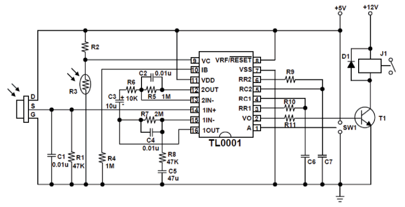
This is not exactly the circuit in the night light, but it comes close. The Nightlight e.g. does not have a relay but 3 bright LED’s are driven. It also does not have a an LDR but a photodiode. The function of the diode (or LDR) is to ensure the night light only works at night. The board also has switch for On-Off and Auto. On using the circuit, it becomes clear that the LED’s stay on for a specified amount of time, that is called the Trigger time. The Trigger time is determined by 24576 xR10 x C6. Once triggered, the chip cannot be triggered again for a certain amount of time that is called the Inhibition time. This inhibition time or Ti is defined by Ti≈24 xR9xC7 (watch out, the Chinese data sheet has switched these two values, the English data sheet is correct). With the current values that wild give a Trigger time of 2.5 seconds and an inhibition time of 0.036 secs. (These values are for the circuit of the datasheet. in the night lamp the on time is abt 5 seconds)
To get rid of the light/dark function, it suffices to replace the photo diode with a resistor in the region of 220kOhm.

The data sheet of the LP0001 shows 3 outputs: Output 1 (on pin 16) and Output 2 (on pin 12) as wel as Vo (on pin 2).
Vo is the detector output that is used to drive a transistor (that drives a relay) and it can be used as such. The other two outputs deliver an analog signal.
Output 1 is the output of an opamp (with + and – input). That has a gain of R7/R8 which is equal to 2M/47K= 40 Output 1 is fed to input 2. That opamp has a gain of R6/R5 = 100. So it seems most logic to pick up the final PIR signal from either opamp 1 or opamp 2. The best seems to be from the Output of opamp 2 on pin 12
What one then only needs to do is to solder a wire to PIN 12 of the chip to pick up the PIR signal and to lead that to an analog input on the arduino.
 After you have soldered the wire connect that to e.g. analog pin 0 on your arduino and connect the Ground as well.
Copy the following program in your Arduino:
int pirPin=0;
  Void setup() {
  Serial.begin(9600);
  pinMode(pirPin, INPUT);
}
  void loop() {
  Serial.println(analogRead(pirPin));
Move your hand to and fro the sensor
theoretically this will give readings between 0 and 1023.
If that works and the sensor readings seem to have at least some correlation with your hand movements that means the sensor works.
One can do several things with this output, e.g. use it to drive an LED or a lamp with analogWrite, or use it for a threshold value above or below which e.g. a lamp or relay is switched on or off.
Whatever one choses, it is generally a good idea to take the average of a few readings and one can do that as follows:
int pirPin=0;
int value=0;
void setup()
  {
  Serial.begin(9600); //just to check
  pinMode(pirPin, INPUT);
  }
void loop()
  {
  value=sample(pirPin);
  Serial.println(value);
  }

int sample(int z)
/* This function will read the Pin 'z' 5 times and
   take an average.
   Afterwards it will be mapped by dividing by 4
   Could of course immediately divide by 20 but this
   way it is easier to follow the program
*/
  {
  int i;
  int sval = 0;
  for (i = 0; i < 5; i++){
  sval = sval + analogRead(z);// sensor on analog pin 'z'
  }
  sval = sval / 5; // average
  sval = sval / 4; // scale to 8 bits (0 - 255)
  return sval;
  }
The digital signal (from Vo) ofcourse can be easily incorporated in a program that reads a digital pin on the Arduino.
EEPROMs on the Arduino with I2C
 Attaching an EEPROM to the Arduino is quite simple and the easiest way to do that is via the I2C bus. EEPROMs come in many forms but the 24 LS256 is a good choice as it is easy to use and pretty cheap (85 euro cents at my supplier). It can hold 256 kilobits of data (that’s 32 kilobytes).
The 24LS256 can also run on 3.3V which is handy if one is using a Lilypad or Pro Mini 3.3V. The 24LS256 uses 3 pins for selection of its address, so you can use up to eight at once on the same bus. 
The above figure shows the base address register of the 24L256. It is addressed as follows: 1010A2A1A0. If you are only working with 1 EEPROM, the easiest is to connect A2-A0 with Ground. This gives the address of 1010000 which is 0x50 Hex. In reading and writing to the EEPROM one needs to realize that it has 32 kB (actually 32767) and therefore one byte is not enough to address all the memory.
So when one wants to send read and/or write requests, one needs to send two bytes – one for the MSB or higher end of the address (the 8 bits from left to right), and the next one for the LSB or lower end of the address (the final 8 bits from left to right).
If for example one wants to use address 21000, that goes as follows: In binary, 21000 is 0101001000001000. Split that up into 01010010 and 00001000, then convert the binary values back to numerical bytes to send with Wire.send().
That sounds more complicated than it is, as there are in fact two operands to help with that. This first one is >>, or bitshift right. This will take the MSB of the byte and drop off the lower end, leaving only the first 8 bits. To get the LSB of the address, one can use operator &, or bitwise and. This operand, when used with 0xFF will give the lower bits.
Writing data to the 24LC256
Writing data is quite easy. First initialize the I2C bus with:
Wire.beginTransmission(0x50); // for pins A0~A2 set to GND
then send some data. The first data to send are the two bytes for the address (25000) were one wants to write to the memory.
Wire.send(21000 >> 8);  // send the MSB of the address
Wire.send(21000 & 0xFF); // send the LSB of the address
Subsequently send the byte to store at address 21000 and then close the connection:
Wire.send(15); //just sending ‘15’  as example
Wire.endTransmission();
That concludes the writing. now for reading:
Reading data from the 24LC256
Reading goes similar. First initialize the connection and provide the address of the data to read:
Wire.beginTransmission(0x50); // Chosen base address
Wire.send(21000 >> 8);  // send MSB of the address
Wire.send(21000 & 0xFF); // send LSB of the address
Wire.endTransmission();
Then, ask for the number of bytes of data starting at the current address:
Wire.beginTransmission(0x50); // base address Wire.requestFrom(0x50,1); // We want one byte
Wire.receive(inbyte);
Here, inbyte is a byte variable chosen to store the data retrieved from the EEPROM.
The Power of the I2C bus is of course that various devices can be connected to the same lines. The top figure shows such a set up with two EEPROMs. It is key of course that they each have their own address. In the figure I have chosen to use addresses 0x50 and 0x51. One gets that by connecting A0-A2 to ground for one chip, but connecting A0 to Vcc (‘ High’) for the second chip. The resulting address is then 1010001.
A print layout i given below

Print design can be found here
