There are many microphone pre-amplifiers available for teh Arduino that are based around common purpose op-amps. An Op-Amp especially suited for audio purposes is the MAX 4466. The Datasheet gives the following application:
In Practice the circuit will look like this. The DC bias for the microphone is taken care of by the resistors R4 and R5. The input capacitor C1 is increased in value to get a better low cut off. The output is rail-to-rail so if the sounds gets loud, the output can go up to Vcc
Vcc is 2.4-5VDC. For the best performance, use the “quietest” supply available (on an Arduino, this would be the 3.3V supply). The output will have a DC bias of Vcc/2 so when its perfectly quiet, the voltage will be a steady Vcc/2 volts (it is DC coupled). If the audio equipment you’re using requires AC coupled audio, place a 100uF capacitor between the output pin and the input of your device. If you’re connecting to an audio amplifier that has differential inputs or includes decoupling capacitors, the 100uF cap is not required. The gain is depending on R5, P1 and R6. If the current gain is not enough, the value of R6 can be decreased, but in that case the value of C4 needs to be increased in order not to influence the Low pass value.
L1 and L2 are ferrite beads that separate the analogue supply from other supply lines
The PFC8574 and the PFC8574A are I2C port expanders that can be uses to connect a parallel LCD to the I2C pins of the Arduino (or other microcontroller)
The PCF8574 has addresses ranging from 0x20 to 0x27 (up to eight PCF8574 devices may be used on the same I2C bus). It’s address is 0100aaay with ‘ aaa’ being the address bits and ‘y’ being the Read(1)/Write(0) bit.
The PCF8574A has addresses ranging from 0x38 to0x3F (up to eight PCF8574A devices may be used on the same I2Cbus). 0x38=0011 1000 (all tied to ground) and 0x3F=0011 1111 (all tied to ‘HIGH’) hand
Addressing takes place with 3 address pins that can be taken high or low and that form the bottom 3 bits of a 7 bit address register (the 8th bit, the least significant bit is the R/W bit).
PCF8574: 0100A2A1A0 0100000 =0x20; 0100111=0x27
PCF8574A: 0111A2A1A0 0111000 =0x38; 0111111= 0x3F
The /INT pin is an open drain output that can be used to trigger events.
NOTE
Though it is always fun to build something yourself. In this case it might not be worth it: consider this ready built board from DealExtreme.com. for only 1.80 euro you will have the complete board, inclusing headers that will solder right into most LCD’s. The PCF8574P as chip alone, will cost you an average of 2.10 euro
Using an LCD for a microcontroller such as the Arduino takes up quite a number of pins and actually doesn’t leave that much pins for other tasks. There are various solutions, like using an HC595 shiftregister (requiring three wires), a PCF 8574 or MCP23008 to create an I2C option or using a shift register such as the 74LS164. The added circuit does just that. It works on an Attiny85 as well.
A 100nf decoupling capacitor is necessary and should be placed near the IC. Shiftregisters as the 74LS164 cause sudden changes to the current drawn from it’s power, and hence introduce noise. To counter this, a “decoupling capacitor” should be used as close to the shiftregister power pins as possible (Vcc and GND). Otherwise, the shiftregister may get faulty data and then the LCD won’t work as intended. This is also dependent on other factors, like wire lengths etc.
The resistor and the diode form an AND gate. They could be replaced by a proper AND gate, but that would increase the component count. The circuit can be easily built on a piece of 16×16 stripboard, even a 11×12 piece if you connect the LCD with wires rather than a connector.
As the top circuit doesn’t really show the logical functions of the 74LS164 but merely the lay out of the chip, I added the circuit below to show its logical function: Program:
It is possible to let the backlight be taken care of by the software as well. Connect the circuit below to pin 4 of the SN164 and to the backlight pins of the LCD:
Backlight
The stripboard should be adapted like this:
With backlight regulation
The full circuit like this:
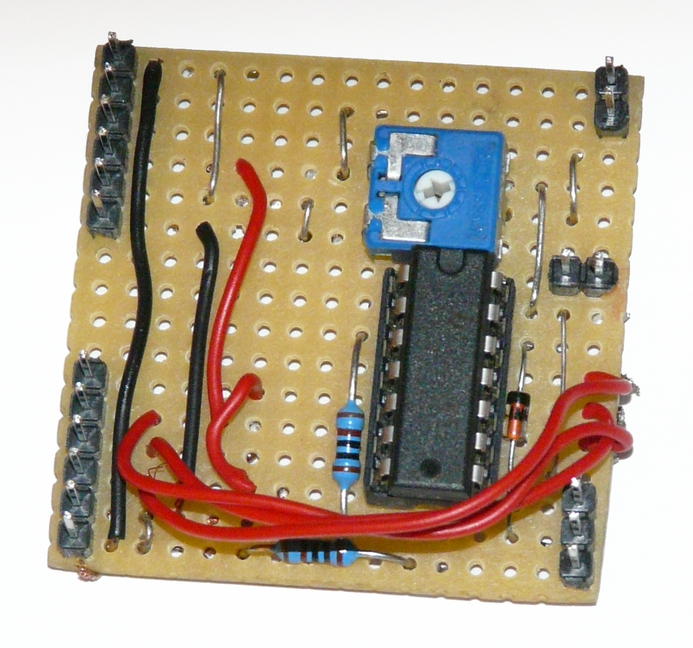
As I still had an old Seiko M1632 display with no back-light and a DIL 2×7 connector rather than a SIL 1×16 connector, I also quickly made a design on perfboard for that:
for Seiko M1632
It is a 9×14 piece. If you are cramped for space you can do it on an 8×11 piece, smaller even if one uses a small standing variable resistor. For the practical circuit I chose a slightly bigger 9×20 piece (no use trimming an already small piece), and no.. you don’t want to see the bottom side 🙂 :
As pin 4 of the 164 is used for the LCD backlight, but the Seiko doesn’t have a backlight, I decided later to add an LED, connected through a 1 k resistor to pin 4 and be able to switch the LED on and off with the backlight command.
With regard to the potmeter for the contrast… if using a potmeter is not desirable for any reason, it is possible to set the Vlc to a voltage that is most optimal for most situations. The circuit shows how. Over the diode a voltage of about 0.65 Volt can be expected which is ideal for most situations:
The above circuit uses an HC164 shiftregister, but Mike’s site also has a circuit for a 595 and a driver program for a PIC as well as an Arduino microprocessor. This circuit does not cater for software backlight control, but it has full 8 bit control, should you need that

 The gain is depending on R5, P1 and R6. If the current gain is not enough, the value of R6 can be decreased, but in that case the value of C4 needs to be increased in order not to influence the Low pass value.