With ELRO AB440, SelectRemote, Powertran, EverFlourish, Eurodomest, Dimmermodule, ProMax, Kambrook, Etekcity, Sonoff/Slampher, Digoo

With the price of 433MHz Receivers and Transmitters being so ridiculously low, I figured I couldn’t put of using some any more so i ordered a pair at Dealextreme for less than 2 USD. When they arrived, of course I imediately wanted to test them.
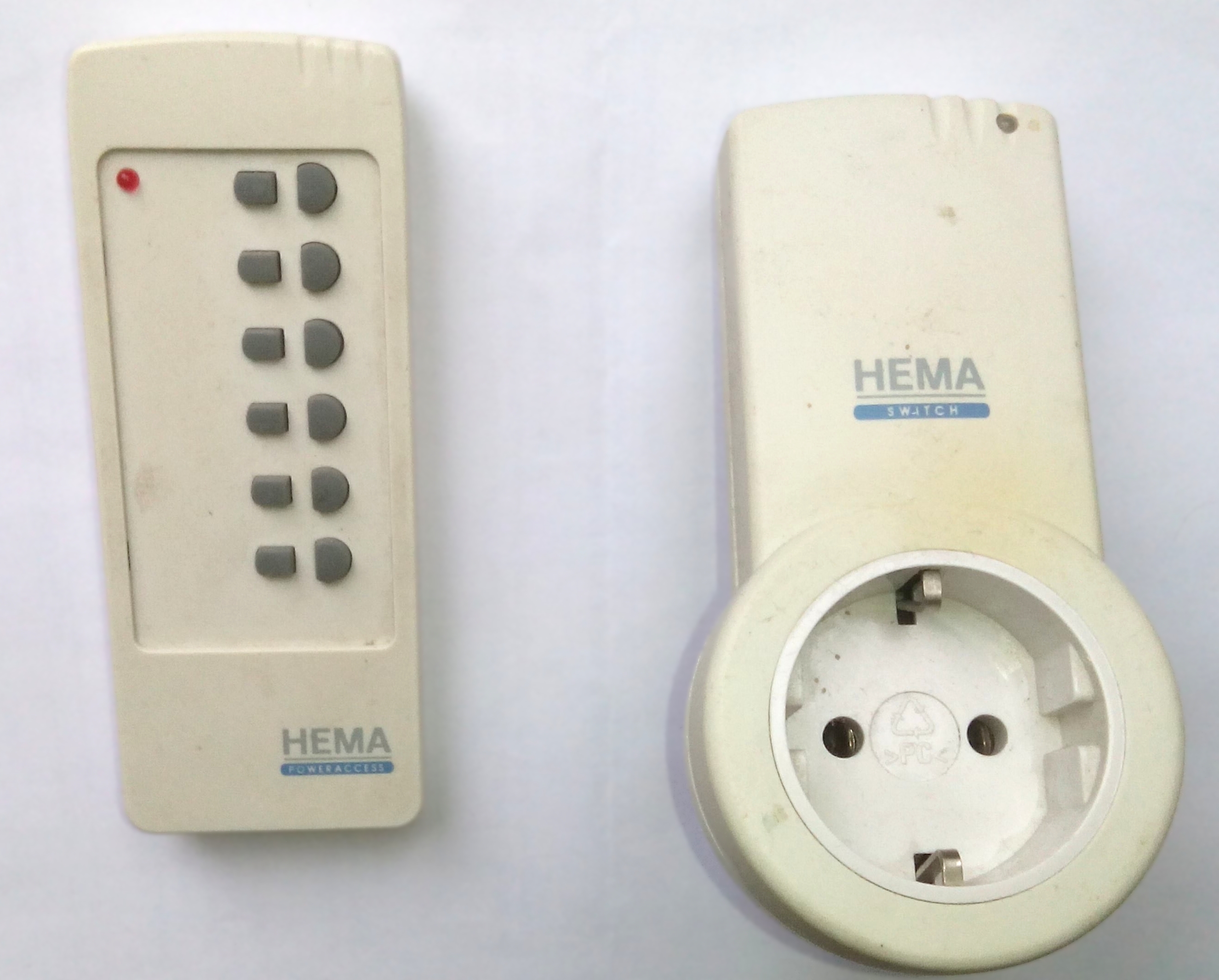
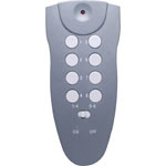
I had an old IKEA set (SELECTREMOTE No. 1728029) also sold by Blokker at one time, and an Old HEMA set (PowerAccess, originally Ewig Industries RF AC socket 288A)) . The Selectremote 1728029 is most likely Equivalent to the Powertran A0342.
As I didnt really have an idea about the codes and as the transmitter of the SelectRemote was broken and the PowerAccess set being a learning one, it seemed best to get a new set. (Actually, the Power Access turned out work on 419MHz, so no way I could have gotten that to work with my set up)
ELRO AB440
My preferred supplier ‘Action’ didn’t have, so on to ‘Blokker’ (both local stores) that had a set: The AB440 for 15 Euro. Apparently the manufacturer was ‘ELRO’. The chip in the remote control is an HX2262, a common chip in RC systems
I loaded one Arduino with an RF sniffer (Datapin on D2) and pressed ‘A on’ and yes, a code came through. pressed again and a different code came through, pressed again and 3 or 4 codes came through. That actually happened in all channels. One code seemed very frequent and I gathered maybe the protocol required to send more than one code, or maybe one code several times.
I decided to focus on just the one ON and OFF button and with just a gentle press, I seemed to come to two codes for the ON and 2 codes for the OFF button that seemed to recur most frequent.
Then I checked if indeed each of those codes had an actual function with regard to the socket being switched on or off, so with my RF sniffer still running, I prepared one of the switches as channel ‘A’ and tested again.
Behold….. it turned out that the Socket switch -in spite of a number of codes being put out by the remote control- only reacted to one specific code and indeed that was one of the two I had opted for.
Though I could analyse the code I figured that if i would just send the code I received the Switch would react to that and that the library would take care of the timing
So, I quickly adapted the Senddemo program to send the On and Off code for Channel A and plugged it back in. and yes, there it went clicking away, On, Off, On, Off.
So now I did the same for the B and C channel, isolated 2×2 codes that seemed the most likely and actually picked the right one immediately to put into the senddemo program and there it was… the 3 socket switches happily clicking away.
Just a few more remarks. As it shows in the output from the ‘Sniffer’ program, it is a 24 bits code. Of course that doesn’t look like any 24 bits code but that is because it is a decimal value. If I calculate the binary code it looks like this. (On and OFF codes) and u just add leading zero’s to come to 24
A 1049937 000100000000010101010001
A 1049940 000100000000010101010100
B 1053009 000100000001000101010001
B 1053012 000100000001000101010100
C 1053777 000100000001010001010001
C 1053780 000100000001010001010100
separated in ‘trits’ it looks like this (the ’29’ is the set number set by the 1st 4 switches):
| on | off | on | on | on | A | B | C | D | na | ON/ | OFF | ||
| 00 | 01 | 00 | 00 | 00 | 00 | 01 | 01 | 01 | 01 | 00 | 01 | 29A | aan |
| 00 | 01 | 00 | 00 | 00 | 00 | 01 | 01 | 01 | 01 | 01 | 00 | 29A | uit |
| 00 | 01 | 00 | 00 | 00 | 01 | 00 | 01 | 01 | 01 | 00 | 01 | 29B | aan |
| 00 | 01 | 00 | 00 | 00 | 01 | 00 | 01 | 01 | 01 | 01 | 00 | 29B | uit |
| 00 | 01 | 00 | 00 | 00 | 01 | 01 | 00 | 01 | 01 | 00 | 01 | 29C | aan |
| 00 | 01 | 00 | 00 | 00 | 01 | 01 | 00 | 01 | 01 | 01 | 00 | 29C | uit |
The first 4 ‘trits’ represent the position of the dip switches that select the group. In my case that was on-of-on-on-on. ‘on’ is ’00’ which means tied to ground. ‘off’ is ’01’ which means ‘floating’. 10111=’23’ (2⁴ +0+ 2² +2¹+2⁰) but if you see the LSB as being on the right -as the library class does- it becomes ’29’ (2⁴+2³+2²+0+2¹)
The next 4 positions determine the Switch ID. The next trits is not applicable and the last two determine ON or OFF.
For RC use there are 2 main libraries for the Arduino: the one of fuzzilogic (Randy Simons) and the RCSwitch from Suat Özgür. As the ELROAB440 set was working with the latter, I initially stuck to the RCSwitch library.
/*
SendDemo - sends RF codes
hacked from
http://code.google.com/p/rc-switch/ by @justy
*/
#include
 // Use whatever number you saw in the RF Sniffer Sketch
#define A_aan 1049937
#define A_uit 1049940
#define B_aan 1053009
#define B_uit 1053012
#define C_aan 1053777
#define C_uit 1053780

RCSwitch mySwitch = RCSwitch();
void setup() {

pinMode(7, OUTPUT); // use pin 7 to drive the data pin of the transmitter.

//
mySwitch.enableTransmit(7);
}
void loop() {

// Send your button's code every 5 seconds.
mySwitch.send(A_aan, 24);
delay(2000);
mySwitch.send(A_uit, 24);
delay(1000);
mySwitch.send(B_aan, 24);
delay(2000);
mySwitch.send(B_uit, 24);
delay(1000);
mySwitch.send(C_aan, 24);
delay(2000);
mySwitch.send(C_uit, 24);
delay(1000);
}
}
Now in hindsight I have been a bit stupid. If I had taken the time to read the documentation of the RCSwicth library, I would have found out that the library caters for 1he ’10 dip switch switches’ such as the ELRO AB440, as is shown in the program ‘TypeA_WithDIPSwitches.pde’
If I would have set the DIP Switches e.g. like “1011100100”, (for device ‘C’) I could have used the statements:
mySwitch.switchOn("10111","00100");
and
mySwitch.switchOff("10111","00100");
Well, let’s say ‘I learned a lot’. Just for completeness sake, it is obvious -if you compare it with the previous table- that the DIPSwitch position ‘ON’ doesnt send a ‘1’ but a zero. The code “1011100100” is that of the ‘C’ switch from the table above.
I still wondered why I couldn’t get the AB440 to work on the fuzzilogic library. With searching further I came upon an extension of the fuzzilogic library called RemoteSwitch (author Jeroen Meijer). That didnt work for the AB440 in first instance but Jeroen was kind enough to work through my data so it now has a separate class for the AB440. (code now on github). (No longer on GitHub but here)
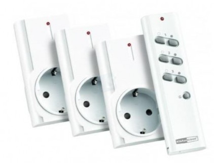
SELECTREMOTE

As I couldnt ‘sniff’ the SELECTREMOTE No. 1728029 for lack of a functioning transmitter, and had no idea what codes it used, (Initially) I couldn’t get it to work yet with the RCSwitch library.
But I did get it to work with the Fuzzilogic RemoteSwitch library, as it was similar to the protocol of a once popular ‘Blokker transmitter’
The code will look like this:
/*
* Demo for RF remote switch transmitter.
* Setup:
* - Connect a 433MHz transmitter to digital pin 7.
*/
#include
// Instance of Blokker remote, use pin 7
BlokkerTransmitter blokkerTransmitter(7);
void setup() {
}

void loop() {
  // Switch on Blokker-device 1.
  blokkerTransmitter.sendSignal(1,true);
  // Wait 2 seconds
  delay(2000);
  // Switch off Blokker-device 1.
  blokkerTransmitter.sendSignal(1,false);
  // Wait 4 seconds
  delay(4000);
}
(Later on I would find the ON and OFF codes to be:
ON 1 : 0011 1111 0000 0011 0000 0000 //4129536
ON 2 : 0000 1111 0000 0011 0000 0000 //983808
ON 3 : 0011 0011 0000 0011 0000 0000 //3343104
ON 4 : 0000 0011 0000 0011 0000 0000 //197376
OFF 1 : 0011 1111 0000 0000 0000 0000 //4128768
OFF 2 : 0000 1111 0000 0000 0000 0000 //983040
OFF 3 : 0011 0011 0000 0000 0000 0000 //3342336
OFF 4 : 0000 0011 0000 0000 0000 0000 //196608
with “0” is 240us on, 740us off
and “1” is 740us on, 240us off)
It is clear that the 8 MSB determine the device address, whereas bits 8&9 determine the ON and OFF state. These codes can be used with the RCSwitch library
With the RemoteSwitch library the coding is as follows:
#include "RemoteSwitch.h"
ElroAb440Switch ab440Switch(7);
BlokkerSwitch3 blokkerTransmitter(7);
 void setup() { }
void loop()
{ //Switch on SelectRemote 1728029 device 1
blokkerTransmitter.sendSignal(1,true);
//Switch on AB440-device B on system code 29.
// dip switch 1-5 is on-off-on-on-on = 10111... but is read as 11101='29'
ab440Switch.sendSignal(29,'B',true);
delay(2000); blokkerTransmitter.sendSignal(1,false);
ab440Switch.sendSignal(29,'B',false);
delay(2000);
}
Powertran A0342
The Powertran A0342 is very akin to the the Selectremote, albeit that it has 8 channels rather than 4, divided over 2 banks that can be selected by a slideswitch on the transmitter. It works with the Blokkerprotocol in the RemoteSwitch library. If you do not want to use a library, because it adds overhead,you can also use the program below, that will also work with the 4 channel Selectremote
https://codebender.cc/embed/sketch:237833
#define radioPin           // IO number for radio output
void setup() {
pinMode(radioPin, OUTPUT); // set data to transmitter pin to output
}
void loop() {
remoteControl(1,0);                     // Turn Remote 1 off
remoteControl(2,0);                     // Turn Remote 2 off
remoteControl(3,0);                     // Turn Remote 3 off
remoteControl(4,0);                     // Turn Remote 4 off
remoteControl(5,0);                     // Turn Remote 5 off
remoteControl(6,0);                     // Turn Remote 6 off
remoteControl(7,0);                     // Turn Remote 7 off
remoteControl(8,0);                     // Turn Remote 8 off
delay(5000);                            // Delay 5 seconds
remoteControl(1,1);                     // Turn Remote 1 on
remoteControl(2,1);                     // Turn Remote 2 on
remoteControl(3,1);                     // Turn Remote 3 on
remoteControl(4,1);                     // Turn Remote 4 on
remoteControl(5,1);                     // Turn Remote 5 on
remoteControl(6,1);                     // Turn Remote 6 on
remoteControl(7,1);                     // Turn Remote 7 on
remoteControl(8,1);                     // Turn Remote 8 on
delay(5000);                            // Delay 5 seconds
}
void remoteControl(int channelNum, boolean remoteState) {
// Turns on or off remote channel
//
// channelNum  : 1 to 8 remote channel number (set on wireless plugpack
// remoteState : 0 = Off, 1 = On
//
// Sends same packet signal 4 times
// 13 Bit pattern in remoteOn and remoteOff arrays

int longTime              = 740;         // microseconds
int shortTime             = 240;         // microseconds
unsigned int remoteOn[8]  = {0x010E,     // 0000 0001 0000 1110
0x010C,     // 0000 0001 0000 1100
0x010A,     // 0000 0001 0000 1010
0x0108,     // 0000 0001 0000 1000
0x0106,     // 0000 0001 0000 0110
0x0104,     // 0000 0001 0000 0100
0x0102,     // 0000 0001 0000 0010
0x0100};    // 0000 0001 0000 0000
unsigned int remoteOff[8] = {0x000E,     // 0000 0000 0000 1110
0x000C,     // 0000 0000 0000 1100
0x000A,     // 0000 0000 0000 1010
0x0008,     // 0000 0000 0000 1000
0x0006,     // 0000 0000 0000 0110
0x0004,     // 0000 0000 0000 0100
0x0002,     // 0000 0000 0000 0010
0x0000};    // 0000 0000 0000 0000

// "0" is 240us on, 740us off, 240us on, 740us off
// "1" is 740us on, 240us off, 740us on, 240us off
// Send order is bit0, bit1, bit2 ... bit 12

// Now send packet four times
for (int j=0; j<=4; j++) {
if (remoteState) {                  // Turn on
for (int k=0; k<=12; k++) {       // Send 13 bits in total
if (!bitRead(remoteOn[channelNum-1],k)) {
digitalWrite(radioPin, HIGH);           // "0"
delayMicroseconds(shortTime);
digitalWrite(radioPin, LOW);
delayMicroseconds(longTime);
digitalWrite(radioPin, HIGH);
delayMicroseconds(shortTime);
digitalWrite(radioPin, LOW);
delayMicroseconds(longTime);
} else {
digitalWrite(radioPin, HIGH);           // "1"
delayMicroseconds(longTime);
digitalWrite(radioPin, LOW);
delayMicroseconds(shortTime);
digitalWrite(radioPin, HIGH);
delayMicroseconds(longTime);
digitalWrite(radioPin, LOW);
delayMicroseconds(shortTime);
}
}
} else {                            // Turn off
for (int k=0; k<=12; k++) {       // Send 13 bits in total
if (!bitRead(remoteOff[channelNum-1],k)) {
digitalWrite(radioPin, HIGH);           // "0"
delayMicroseconds(shortTime);
digitalWrite(radioPin, LOW);
delayMicroseconds(longTime);
digitalWrite(radioPin, HIGH);
delayMicroseconds(shortTime);
digitalWrite(radioPin, LOW);
delayMicroseconds(longTime);
} else {
digitalWrite(radioPin, HIGH);           // "1"
delayMicroseconds(longTime);
digitalWrite(radioPin, LOW);
delayMicroseconds(shortTime);
digitalWrite(radioPin, HIGH);
delayMicroseconds(longTime);
digitalWrite(radioPin, LOW);
delayMicroseconds(shortTime);
}
}
}
delay(5);              // Short delay between packets
}
delay(10);                // short delay after sending
}
EverFlourish EMW203RW
Another popular RC system is the Chinese EverFlourish EMW203RW from the German DIYMaxeda group (Praxis, Formido, Brico, Plan-It). It is a sturdy outdoor (green) or indoor (white) switch with a transmitter for 3 switches. They can be set to 4 channels. Were sold as Cotech by Clas-Ohlsson
|
|
|


The 24 bit codes (for Channels A and B) are as follows: (on-off / decimal-binary)
A1 1381719 1381716 / 000101010001010101010111 000101010001010101010100
A2 1394007 1394004 / 000101010100010101010111 000101010100010101010100
A3 1397079 1397076 / 000101010101000101010111 000101010101000101010100
B1 4527447 4527444 / 010001010001010101010111 010001010001010101010100
B2 4539735 4539732 / 010001010100010101010111 010001010100010101010100
B3 4542807 4542804 / 010001010101000101010111 010001010101000101010100
To make sense of this code, it is easiest to separate them in ‘trits’. Let’s look at the ‘on’ code for ‘A1’ :
| 00 | 01 | 01 | 01 | 00 | 01 | 01 | 01 | 01 | 01 | 01 | 11 |
| A | B | C | D | 1 | 2 | 3 | na | na | na | na | ON |
The first four trits set the device_address (A-D) with a selected letter grounded (00) and the nonselected floating (01)., the next 3 the Switch id (1-3) then there are 4 non relevant trits and then one trit for on (11=High) or off (00=grounded).
‘B1-ON’, according to that logic, should then be:
| 01 | 00 | 01 | 01 | 00 | 01 | 01 | 01 | 01 | 01 | 01 | 11 |
| A | B | C | D | 1 | 2 | 3 | na | na | na | na | ON |
which -as we can see in the sniffed code- is correct. This code looks very much like the one for the ‘Blokker2’ class in the addition Jeroen Meijer made to the fuzzylogic library. It now has a separate class. (Library moved here)
#include "RemoteSwitch.h"
EverFlourishSwitch everswitch(7);
void setup() {
}
void loop() {
  everswitch.sendSignal('A', 1, true);
  //wait 2 seconds
  delay(2000);
  everswitch.sendSignal('A', 1, false);
  delay(2000);
}
EuroDomest 972080
‘Action’ is currently selling the EuroDomest 972080 system: 3 switches + remote control for 9.99 euro. This is a learning system that will not lose the
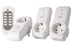
settings if taken out off the wall-socket (at least not for a while. These receivers supposedly can learn the old kaku_switch protocol. They are receptive to remotes of other systems when programmed as such, but I found that they do not always recognize the codes sent by other remotes during programming so you may only be able to only switch on or off a lamp when programmed with another remote.
The manual of the Eurodomest is a a bit cryptic in how to program the switches. This is how it is done:
Plug in a switch and push the ON button on the switch until the led starts flashing slowly. Then push the ON button on the remote: the LED on the switch now should start to flash quickly. Press the OFF button on the remote toll the LED goes off. Your switch is now programmed. (on second thought, most likely pressing the OFF button isnt even necessary)
The remote (at least in my case) sends the following codes:
Channel 1 ON/OFF
Received 9588047 / 24bit Protocol: 1 100100100100110101001111
Received 9588046 / 24bit Protocol: 1 100100100100110101001110
Channel 2 ON/OFF
Received 9588045 / 24bit Protocol: 1 100100100100110101001101
Received 9588044 / 24bit Protocol: 1 100100100100110101001100
Channel 3 ON/OFF
Received 9588043 / 24bit Protocol: 1 100100100100110101001011
Received 9588042 / 24bit Protocol: 1 100100100100110101001010
Channel 4 ON/OFF
Received 9588039 / 24bit Protocol: 1 100100100100110101000111
Received 9588038 / 24bit Protocol: 1 100100100100110101000110
Channel ALL ON/OFF
Received 9588034 / 24bit Protocol: 1 100100100100110101000010
Received 9588033 / 24bit Protocol: 1 100100100100110101000001
It is clear to see that the signal only changes by 1 bit, though it is a bit odd that there seems to be an unlogical difference between channel 3 and 4 as one would expect “100100100100110101001001” for ON and “100100100100110101001000” for OFF.
Also the All ON/OFF seems a bit out of order.
Sending these codes as is with the RCSwitch library works fine. It seems impossible to figure out what the device code for a random set would be, so you would need to first sniff the remote control, or, just send a chosen code with a 433MHz transmitter from an Arduino (or other micro controller).
The Eurodomest protocol is very akin to that of the ENER002, that in itself is akin to the Duwi/Everflourish EMW200R. It has the HS2303-PT chip rather than the PT2262. The Eurodomest might be the same as the Bauhn remote switch set. The ENER002 has its own class in the Jeroen Meijer update of the Fuzzilogic library. ( Now on gitlab.)
If you want to use channel 4, make sure you have the most recent update of the Jeroen Meijer library
Program would look like this:
#include "RemoteSwitch.h"
Ener002Switch enerswitch(7);
void setup() {
}
void loop() {
enerswitch.sendSignal(823148, 1, true); //channel 1
delay(1000);
enerswitch.sendSignal(823148, 1, false);
delay(1000);
enerswitch.sendSignal(823148, 2, true); //channel 2
delay(1000);
enerswitch.sendSignal(823148, 2, false);
delay(1000);
enerswitch.sendSignal(823148, 3, true); //channel 3
delay(1000);
enerswitch.sendSignal(823148, 3, false);
delay(1000);
enerswitch.sendSignal(823148, 4, true); //channel 4
delay(1000);
enerswitch.sendSignal(823148, 4, false);
delay(1000);
enerswitch.sendSignal(823148, 7, true); // ALL
delay(1000);
enerswitch.sendSignal(823148, 7, false);
delay(1000);
}
The ‘823148’is the decimal form of the first 20 bits that form the set address (for a particular Transmitter)
If you do not have that number… just use any 20 bits number, and use the arduino to program your Eurodomest. The ‘7’ means ‘All’. As per Januari 2016 the Eurodomest is phased out at the Action stores and is being replaced by the ProMax. The Eurodomest is the same one as the Efergy remote (Efergy Easy Off).
LED Dimmer
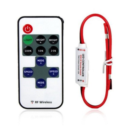
The full credit of this goes to Jeroen Meijer who analysed the protocol of a popular RF Led dimmer driver available in Chinese webshops.
The code is very akin to that of the Eurodomest, albeit that it has a 19 bit address and a 5 bit command structure.
His fork of the RemoteSwitch library contains a class -CnLedDim1Switch- to control this dimmer.
The codes are also easy to snif. The left 19 bits forming the base address of the device.
So if pressing the button ‘ON’ generates the code:
on 6670849 / 0110010111001010000 00001,
then ‘0110010111001010000’ or ‘208464’ is the baseaddress and ‘00001’ the command code.
A program would be like this:
#include "RemoteSwitch.h"
CnLedDim1Switch ledDimSwitch(7);
const unsigned long dimaddress = 208464;
const byte pwr = 1;
const byte licht = 4;
const byte BrightUp = 5;
const byte BrightDown = 6;
const byte Full = 7;
const byte Half = 8;
const byte Quart = 9;
const byte Mode = 11;
const byte SpeedUp = 13;
const byte SpeedDown = 15;

void setup(){}

void loop()
{
ledDimSwitch.sendSignal(dimaddress,Quart);
delay(1000);
ledDimSwitch.sendSignal(dimaddress,Half);
delay(1000);
ledDimSwitch.sendSignal(dimaddress,Full);
delay(1000);
}
ProMax 75.006.14 / Elro Flamingo F500S
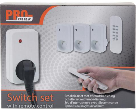
The Promax 75.006.14 is currently (early 2016) sold at Action stores (Netherlands) as a follow up for the Eurodomest. It is a sleek design, but appears to be difficult to implement. As it turns out the transmitter sends out several protocols.
.
Although you may find reference on internet that the transmitter of this set sends two codes per key, that is in fact not true: it sends 4 codes per key. Two of those codes can be found with the RCSwitch library sniffer and 1 can be found with the RemoteSwitch library sniffer example. The RC found protocols are apparently the ‘AC’ protocol and the HomeEasy EU protocol. The RemoteSwitch-found protocol seems to be a Kaku2 protocol, but sadly none of those codes work on the ProMax Switches. For that you need the 4th code (actually it is the 1st code it doesnt detect).
There are several ways to find that code. You could use the so called “Poor man’s oscilloscope” in which you connect the soundcard of your computer via a voltage divicer to a 433MHz receiver, record the keypushes with Audacity and try to work out from there what the codes of your transmitter are. There is also another way:
As device the ProMax is akin to the Elro Flamingo F500S therefore it is the Flamingo sniffer program that could be used. This renders 28bits codes, add a zero on the end to make it fit a uint32_t bit word. The Promax is similar to the Elro Flamingo F500S, Mumbi m-FS300 and possibly the SilverCrest 91210. As the the Promax protocol has rolling code per key, you may find 16 different codes per key. Take one, if that does not work, pick another. As during pairing with your tansmitter you only need to send the ON code, after wich the switch knows how to react to the off code and the master buttons, it is obvious there is a relation between the ON and OFF codes. In fact, the OFFcode can be calculated from the ON code. Each ProMax can be programmed with 5 codes. Be carefull to not program it with randomcodes, because you need the corresponding OFF code to remove the code.There is also another way. Find some working Flamingo codes from the internet and program your switches with those and use this program to send the codes from yr arduino. As the promax has the possibility to store 5 codes per switch, you can also program it with the Remote. That way you have switches that react to the remote as well as to the Arduino. Once you have founde the codes, having your arduino send them to the Switch is fairly easy: First send a sync signal that is HIGH for 300usecand low for 1500usec. Then send a ‘0’ (bit) as HHHL with a periode of 300uS and the ‘1’ as HLLL. The Class Ohlson Co/Tech 51058×10 is probably similar too, albeit that its sends 4 rolling codes
Beware, the ProMax sold at action is NOT this one.
Flamingo SF-500WD/2
 In the fall of 2017 Action started selling the Flamingo SF-500WD/2 remote for 9.95 euro whereas regular retail price is arond 17 euro. The SF-500WD/2 is a 2 switches-1 remote Outdoor remote set for which i have not been able to find any codes yet. Apparently it is recognized by RFlink. A manual is available.
Kambrook RF3399
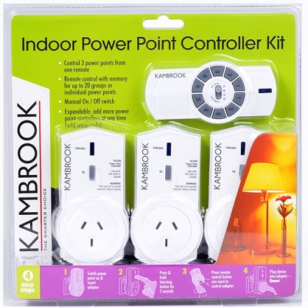
The Kambrook, made by Ningbo, is a bit of a different RF switch as the RemoteSwitch and RCswitch libraries don’t detect it as it has a 48 bit packet size. A fork of the RCSwitch library has a 4th protocol added to make it work with the Kambrook.
In the Kambrook a short pulse is constructed from a 280uS wide pulse, followed by 300uS off period. The long pulse consisted of a 675uS wide pulse, followed by a 300uS off period. The message is repeated 5 times with a gap of 9850us in between.
The signal consists of 48 bits: it starts with an 8 bit sync signal thart is typically 01010101. That is followed by 24 (3×8) address bits. Then 8 databits, followed by 8 trailing bits, typically 11111111.
The databits determine the switch and wether it is on or off
| Unit | Data | Data (decimal) |
| A1 ON | 00000001 | 1 |
| A1 OFF | 00000010 | 2 |
| A2 ON | 00000011 | 3 |
| A2 OFF | 00000100 | 4 |
| A3 ON | 00000101 | 5 |
| A3 OFF | 00000110 | 6 |
| A4 ON | 00000111 | 7 |
| A4 OFF | 00001000 | 8 |
| A5 ON | 00001001 | 9 |
| A5 OFF | 00001010 | 10 |
| B1 ON | 00000101 | 17 |
| C1 ON | 00100001 | 33 |
| D1 ON | 00000001 | 49 |
Arduino code for the Kambrook is here.
- Reverse engineering the RF protocol on a Kambrook Power Point Controller
- Kambrook Remote Power Outlet & Arduino – working
- Home automation with the raspberry pi
Nexa, Proove, Anslut
 Details on how to drive these switches is described here, and here more on the Ikea Ansluta., and the Nexa.
The Nexa looks a lot like the KlikAanKlikUit APA3-1500R, which -in lieue of a transmitter- can be programmed by the transmitter of the Action ProMax 75.006.14 / Elro Flamingo F500S
Kaku APA3 1500R
This set is a selflearning set, that is catered for in the Remote Switch library. The transmitter can be used to program the receivers, but it is also possible with a program like:
#include "RemoteSwitch.h"
KaKuSwitch kaKuSwitch(11);
void setup() { }
void loop() {
 	kaKuSwitch.sendSignal('A',1,true);
 	delay(2000);
        }
That will set the switch to “Switch A, channel 1” after wich
kaKuSwitch.sendSignal('A',1,true);
kaKuSwitch.sendSignal('A',1,false);
will switch it ON or OFF.
As said above: In lieue of a transmitter, the APA3 1500R can be programmed by the transmitter of the Action ProMax 75.006.14 / Elro Flamingo F500S
Etekcity
 Etekcity is a popular brand that has several types. The popular 5Rx-2TX/learning code consist of 5 outlet switches and 2 transmitters. The transmitters have 5 ON and 5 OFF buttons. The coding is rather simple: it has a 24 digit code in which the last 4 bytes signal ON (0011) or OFF (1100). The next 5 byte pairs (so bit 4 to bit 13) indicate the number of the button (both bytes in pair 1-5 high if button 1-5 is pressed. bytes 4-7 are always ‘0’ unless the button for that position is pressed, bytes 8-13 are always ’01 unless the button for that position is pressed. The remaining bytes form the base address of the hand transmitter. The pulswidth is 190uS. The below table clarifies it:
| Button | On/Off | address | 5 | 4 | 3 | 2 | 1 | Off/On |
| 1 | “on” | 00 00 01 01 01 | 01 | 01 | 01 | 00 | 11 | 0011 |
| “off” | 00 00 01 01 01 | 01 | 01 | 01 | 00 | 11 | 1100 | |
| 2 | “on” | 00 00 01 01 01 | 01 | 01 | 01 | 11 | 00 | 0011 |
| “off” | 00 00 01 01 01 | 01 | 01 | 01 | 11 | 00 | 1100 | |
| 3 | “on” | 00 00 01 01 01 | 01 | 01 | 11 | 00 | 00 | 0011 |
| “off” | 00 00 01 01 01 | 01 | 01 | 11 | 00 | 00 | 1100 | |
| 4 | “on” | 00 00 01 01 01 | 01 | 11 | 01 | 00 | 00 | 0011 |
| “off” | 00 00 01 01 01 | 01 | 11 | 01 | 00 | 00 | 1100 | |
| 5 | “on” | 00 00 01 01 01 | 11 | 01 | 01 | 00 | 00 | 0011 |
| “off” | 00 00 01 01 01 | 11 | 01 | 01 | 00 | 00 | 1100 |
As it is a learning remote, one will have to sniff the code of the transmitter, or use the code above.
 Another popular Etekcity model has a remote with only 5 buttons for on and off. The code here is fairly simple as well as shown in the table below
| button | Address | 5 | 4 | 3 | 2 | 1 |
| 1. | 00 01 11 01 01 01 01 | 00 | 00 | 00 | 00 | 11 |
| 2. | 00 01 11 01 01 01 01 | 00 | 00 | 00 | 11 | 00 |
| 3. | 00 01 11 01 01 01 01 | 00 | 00 | 11 | 00 | 00 |
| 4. | 00 01 11 01 01 01 01 | 00 | 11 | 00 | 00 | 00 |
| 5. | 00 01 11 01 01 01 01 | 11 | 00 | 00 | 00 | 00 |
PulseLength: 162 microseconds Protocol: 1
Intertechno
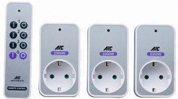 The PB3-230 is a remote powerswitch made by Intertechno. The are also sold under the name ARC PB3-2300 or Nexa PB3-2300. There is a library available.
SonOff/Slampher
 The Sonoff and Slampher are two devices sold by Itead. They come in several versions either controlled by WiFi, by RF or by both. The transmitter is a 4 button device (beware, it is often sold seprately) that sends out 24 bit codes in which the first 20 bits are the same and the last 4 just indicate binary 1, 2, 8 or 16.
These buttons can control 4 sonoffs as they are meant as toggle buttons rather than On/Off buttons. The set up is as follows: Quickly press “SET” button on Sonoff and Slampher twice, the red LED on Sonoff/Slampher will flash one time, then press one of the ABCD buttons on the controller once for a few seconds for pairing. If you pair it with A, then you can press A to turn on/off your device. The transmitter sends the following codes:
| Button | Decimal | Binary |
| A | 11708433 | 10110010101010000001 0001 |
| B | 11708434 | 10110010101010000001 0010 |
| C | 11708436 | 10110010101010000001 0100 |
| D | 11708440 | 10110010101010000001 1000 |
As the WiFi use of the sonoff and slampher is through a specific website, there are many software hacks available (it contains an ESP8266). If you reflash it with new software, there is no garantee that the RF function will be kept.
Digoo RC-13
 The Digoo RC-13 Smart Home RF Wireless Remote Control Socket comes with 3 sockets and either a 3 channel or a 5 channel remote.
the remote transmits the following 24 bit codes
| 1 ON | 10001111111000110000 1001 |
| 1 OFF | 10001111111000110000 0001 |
| 2 ON | 10001111111000110000 1010 |
| 2 OFF | 10001111111000110000 0010 |
| 3 ON | 10001111111000110000 1100 |
| 3 OFF | 10001111111000110000 0100 |
It is clear to see that the device number is defined in the last 3 bits, whereas the ON/OFF code is defined in the 4th bit from the right. The first 20 define the ID of the set. The Transmitter is based around the EV1527 chip. The encoding protocol is the same for every EV1527 device. 24bit total, the first 20 bit is the ID or address and the last 4 bit are data.
The timing is the duration of one bit (bit length) and is defined as 256 clock cycli. A resistor and a capacitor define the frequency of the clock oscillator. It is explained in the datasheet.
Some further 433 resources:
A new way to interface with remote power switches
How to operate Low Cost Outlets
433 MHz rf module with Arduino Totorial
Decoding and sending 433 MHz Rf codes with Arduino and RC switch,
433 MHz rf module with Arduino Totorial
Some usefull example codes for the Arduino on github:
Handy RF sniffer (Datapin on D2) and Senddemo sketch (Datapin on D7).


