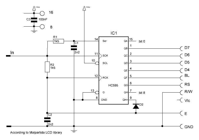
The one wire LCD interface has been around on the internet for some time already and made popular by Roman Black, although he claims he is not the inventor of the principle. His article is mainly PIC processor oriented, but it gives a good explanation of the principle. Myke Predko is also a name that should not be unmentioned as pioneer in 1 wire LCD driving. Also this article about one wire driving of a shift register is very informative
The ShiftRegLCD123 website from Raron used to give a lot of information as well, along with circuits, but that (the Wiki) seems to have disappeared. But his library is in codebender.
In brief, the One Wire interface uses a latched shift register in which the clock and the latch are taken from the data signal through two RC networks that produce the necessary delay. Circuits are a plenty on the interweb, but finding the proper driver for it can be confusing sometimes.
Although the interface on the data, clock and latch lines is rather standard, the connection between the shift register and the LCD has thre major variants that for now i will just call the Roman Black, the LCD3Wire circuit (yes, it is 1 wire) and the ShiftRegLCD123 circuit. Also Elektor has published a 1 wire interface (Detlef Hanemann)(Published in issue 9/2015 on page 92) with yet again a different shift register to LCD connection. Their setup is said to have several advantages over the setup used by Roman Black, it uses the Q7′ direct output of the shift register to trigger the output latch register to carry over automatically the shifted data to the output pins. But for that it requires a monoflop built around a BS170 FET to generate the E-pulse. The setup to be used in Francisco Malpartida’s LCD library is yet again different from the other 3 and uses a diode to create an AND gate
ShiftRegLCD123
Malpartida LCD library
| . | Roman Black | LCD3Wire | Shiftreglcd | Elektuur | Malpartida |
| RS | Qc | Qb | Qc | Qg | Qg |
| R/W | GND | Qc | GND | GND | GND |
| E | Qd | Qd | Qh | Qh’ | Qh’ sort of |
| D4 | Qe | Qh | Qd | Qa | Qe |
| D5 | Qf | Qg | Qe | Qb | Qd |
| D6 | Qg | Qf | Qf | Qc | Qc |
| D7 | Qh | Qe | Qg | Qd | Qb |
Driving these OneWireLCD’s thus differs per configuration. The ShiftRegLCD123 library can do both the ShiftRegLCD and the LCD3Wire protocol. The Liquid Crystal Library of Francisco Malpartida does have a One Wire protocol but make sure you have the latest version. However, it relies on connections different from the others mentioned:
// Bit #0 (QA) – not used
// Bit #1 (QB) – connects to LCD data input D7
// Bit #2 (QC) – connects to LCD data input D6
// Bit #3 (QD) – connects to LCD data input D5
// Bit #4 (QE) – connects to LCD data input D4
// Bit #5 (QF) – optional backlight control
// Bit #6 (QG) – connects to RS (Register Select) on the LCD
// Bit #7 (QH) – used for /CLR on the HW_CLEAR version (cannot be changed)
// (Q’H) – used for Latch/EN (via the diode AND “gate”) (cannot be changed)
// -----------------------------------------------
//
//                         74HC595     (VCC)
//                       +----u----+     |          2.2nF
// (LCD D7)------------1-|QB    VCC|-16--+      +----||----(GND)
// (LCD D6)------------2-|QC     QA|-15         |
// (LCD D5)------------3-|QD    SER|-14---------+--[ Resistor ]--+
// (LCD D4)------------4-|QE    /OE|-13--(GND)         1.5k      |
// (BL Circuit)--------5-|QF    RCK|-12---------+                |
//                       |         |             \               |
// (LCD RS)------------6-|QG    SCK|-11-----------)--------------+--(Seri
//                     7-|QH   /CLR|-10--(VCC)   /               |
//                  +--8-|GND   Q'H|--9---|<|---+--[ Resistor ]--+
//                  |    +---------+     diode  |      1.5k
//                  |                           |
//                  |      0.1uF                |
//                (GND)-----||----(VCC)         +----||----(GND)
//                                              |   2.2nF
// (LCD EN)-------------------------------------+
// (LCD RW)--(GND)
//
The Elektuur/Elektor configuration has its own program, or here (both direct download link)


