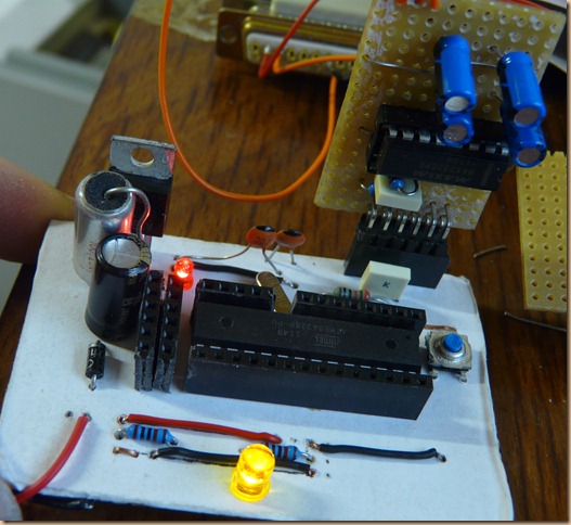
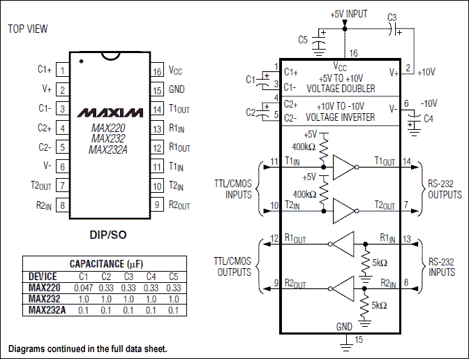
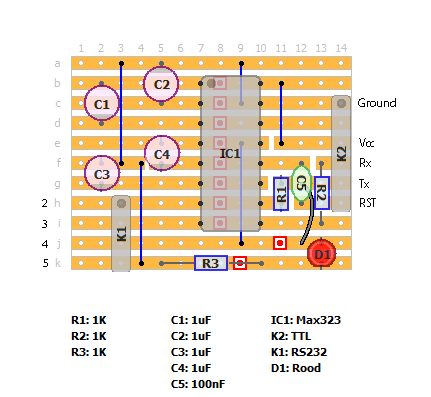
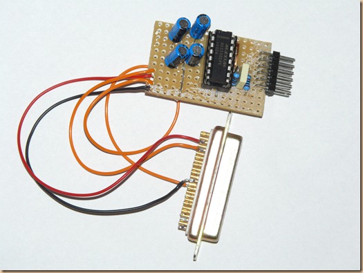
A connection between a computer and a self build Arduino (or other microcontroller) is easy to make with a MAX232 chip. The figure below is an almost classic design. It is according to the october 2002 revision of the datasheet: C4 is connected between pin2 and earth, while in other designs it is connected between pin 2 and Vcc (kathode on Vcc). This circuit just worked for me. I guessed that if pin 2 has a higher potential than Vcc, it also has a higher potential than ground. In some circuits you will also find it connected between pin 2 and 6
In principle you could do with only 2 signals (Tx and Rd), but I have added a reset that is connected to the RTS signal on the subD connector (Via the Max232 of course) 
Just for some clarification: Normally with a serial communication set up, the Tx signal of one device, is connected to the Rd pin of the other device. In this circuit, that is taken care of on the SubD connector: Pin 3 is the Tx signal, that goes to the RdIn (pin 8) of the chip. It is converted in voltage in the chip, then goes to RdOut on pin 9. That pin –though called Rd- then goes to the Rd pin on the Arduino/Atmega/Pic. The connection between Tx and Rd already has been made, no need to switch that again.
Same for the Tx signal of the microprocessor: It attaches to pin10 on the Max232, is converted and appears on pin 7 of the chip and then is brought to the Rd pin on the SubD connector. The DB9 plug in th epicture is a female plug looked at from the solder side.
If for any reason one would prefer to use an old SubD25 serial connector, the table below shows the corresponding pins between the two. To make things a bit confusing both pin 2 and 3 have exactly opposite functions on these connectors.
| DB9 | Signal | DB25 |
| 1 | DCD | 8 |
| 2 | Rd | 3 |
| 3 | Tx | 2 |
| 4 | DTR | 20 |
| 5 | SGnd | 7 |
| 6 | DSR | 6 |
| 7 | RTS | 4 |
| 8 | CTS | 5 |
| 9 | Ri | 22 |
The LED’s and resistors R3 and R4 are not really necessary, they just give a visual indication of the transmitting signals, choose a nice color.
R1 and R2 are in fact also not necessary, but they offer some form of protection should you wire up wrong (like connecting to the wrong pin on your microprocessor)
Once the circuit is build, then first test it before you attach it to your Arduino. The easiest way to test it is to temporarily connect the Tx and Rd pin (so the ends of R1 and R2) with eachother. Apply 5 volts to the chip and connect your serial cable.
Open up the Arduino IDE, select the proper COM port under ‘Tools’, open up the serial monitor and type in some characters and click ‘Send’. The characters should be echo-ed back.
For me this worked with all baud-rates.
Then disconnect the temporary connection you just made and connect Tx and Rd to the corresponding pins on your board/chip.
If that has the bootloader installed, you should be able to upload a program to your board with this serial connection.
Worked like a charm
 |
Note: Many ‘modern’ computers that still have a serial connector do in fact already not work with the high voltages that we know from true RS232 and then the MAX232 might not be needed, but one could use a levelshifter as e.g. Sparkfun is selling ($6.95) and try to build that yourself. It is not a big circuit, but in my idea, usung the MAX232 is just easier and the RS232Shifter board is actually a bit of a hack and does not seem as reliable.
Lots of RS232 info here. and here
Another one here, and here, and here, and here, and here, and here (Thai)


