Various webstores sell a FET module that is aimed at switching high current loads with an Arduino or even a Raspberry pi.
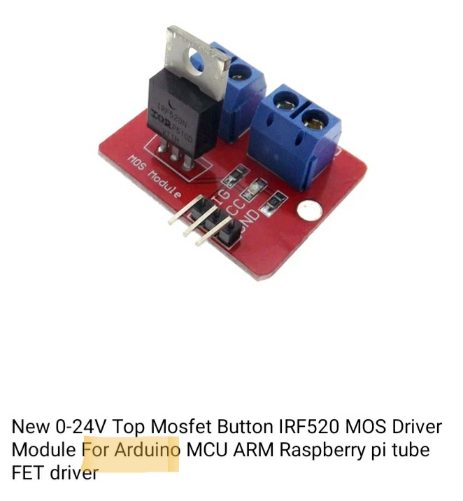
The module seems quite handy, especially if you do not like soldering. It has everything you need, including handy screw connectors for that heavy load you plan to switch. A quick glance on the specs tells you it can deliver 9.7 amps at a 100 Volts and it has a resistance (Rdson) of 0.2 ohm and it is “for the Arduino” so you should be fine right?
Well….not really. The FET used, the IRF520 is not really suitable for the logic levels the Arduino is working with, let alone the 3.3Volt levels of the Raspi. The IRF520 is more at ease with 10 Volt gate voltage. I wrote a post on this subject a while ago.
Using Mosfets with TTL levels.
Power LED Drivers.
So suppose you just bought a couple of those modules. Can’t you use them at all?
Well… maybe but let’s have a look at the datasheet first. In the ‘electric characteristics’ it says that the treshold Vgs, that is the voltage between gate and source (usually ground) should be 2-4 volts for the FET to start conducting. That sounds great -as the Arduino delivers 5 Volt- but it isn’t. At the threshold Vgs the current flowing is only minimal, in this case 250uAmp. That is not a current you bought a powerfet for.
But, i hear you say, the arduino delivers 5 volt, surely 5 Volt should be OK. Well if we again look in the datasheet (Fig 3), yes 5 Volt looks a bit better

At 5 Volt the module should be able to deliver some 4 Amps and that ofcourse is not bad. But there is a caveat. Section 28.2 of the atmega328 datasheet says that the HIGH output voltage of the I/O pins is 0.7 Volt lower than the Vcc. So let’s take the scenario in which you are using a phone charger to power your arduino and it only provides 4.8 volt. The Arduino output then will be 4.1 volt. That brings the drain current in the 250uA range again. That’s not good.
So what to do? Well if you were smart you’d say ‘lesson learned’ throw them in a box and buy a decent logic level FET e.g. the IRL520. That one can deli er some 9 amps on a 4 volt gate to source voltage. Sadly however those do not come on such a handy little board as this IRF520 module. ( the IPP096N03L however is probably an even better choice than the IRL 520)
If you really want to use the IRF520 module, coz you hate to let it go to waste, there are some options, but these are only practical if you have say a 12 volt source availeble, for instance if you wanted to use the module to drive a 12 Volt load:
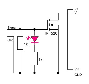
Use a transistor to drive the FET: usually this is done by pulling up the gate to 12 volt with a 10k resistor and switching the gate to LOW with a transistor (e.g. a BC547). (This will invert the signal though). Like so:

In this case however that will not work because the module contains a 1k pulldown resistor. So when the transistor receives a LOW on its base to switch the FET on the 10k will form a voltage divider with the 1k, rendering only 1 volt on the gate. So we would need to remove the pull down resistor. It is the resistor directly next to the SIG label. Most likely you would also need to remove the LED (next to Vcc label) or its 1k seriesresistor (next to GND label).

 A more elegant method is using an optocoupler such as the ubiquitous PC817 to drive the FET. A look at the datasheet tells us it has a max collector current of 50mA and a Vce of 0.2Volt in saturation.

Thus when the optocoupler opens a current of 12/500=24mA will flow (500 because the module has 2x1k resistor on the input). The voltage on the gate will be 12-0.2Volt.
Should you still looking to buy a ready to use MOSFET module, consider the D4184 module


really complete and detailed. Thank you
My pleasure. Glad you like it
Thanks a lot E, I wondered if I broke one of my modules, then stumled over your post just to learn that the MOSFET is misdimensioned. I have two modules, one works with RPi, one doesn’t. Since I would like to use the PCB and other components on the modules, I decided to desolder the IRF520 and exchange them by IRLZ 44 and hope that does the trick.
My pleasure. Just from the top of my head the IRLZ44 does have more suitable specs. Not sure if it is really worthwhile to desolder the IRF520 as opposed to just put the IRLZ44 on a piece of PCB but you are the best judge of that.
Hello, Very nice and informative blog, i want to use IRF540n mosfet with pwm 3.3v from esp8266, but as blog mention its saturation voltage is high, i already ordered PC817 optocouplers, but now i realize it might be slow for PWM, can i use these optocouplers with mosfet to generate PWM 12v, with load consuming maximum 10A?
Hi, yes you should be able to do that. The typical rise and fall time of the pc817 is around 4 usec. (but could be a bit slower) which would determine your max pwm frequency though. Another factor to consider is the gate capacity of the IRF540N, which is around 1800 pF i think, which makes it not the fastest on the block
Thank you very much for your help!
I want to make LED light strip dimmer with this mosfet and with esp8266 running esphome. I read somewhere that for lights pwm of upto few KHz is enough. considering worst case timing of pc817 it can still work with upto 55KHz. and i don’t understand the other part of your answer, IRF540N has gate capacitance of 1960 pF, how does it affect pwm switching, Sorry but i am new to switching devices.
This is datasheet of FETs from the same brand i own.https://pdf1.alldatasheet.com/datasheet-pdf/view/68172/IRF/IRF540N.html
Should indeed be enough for dimming. The gate capacitance of a FET is determining the speed with which the gate can reach the required voltage, similar to charging a capacitor
The 330 ohm resistor between arduino and octocoupler isn’t mentioned besides it being in the diagrams, is this resistor really necessary? I’m using a Raspberry Pi Pico.
It is there to protect the microcontroller. The forward voltage of the pc817 is 1.2 volt. The raspberry pi pico has an output voltage of 3.3 volt, which is a 2.1 volt difference. That needs to go somewhere. If there is no resistor the current through that gpio pin that is controlling could runup dramatically. The 817 can withstand 50mA but the pi can’t really (or at best it is a very unhealthy level). Besides, the current may run up even more. For the circuit with the transistor the situation would even be worse as the base voltage is 0.6 volt, giving a 2.7 volt difference. The 330 ohm resistor limits the current to about 6 mA which is quite sufficient.