Years ago I published a TRIAC dimmer that could be controlled by a simple microcontroller such as an arduino. Times have changed and right now it is of more importance to be able to control that lamp from a home automation system such as OpenHab, Homematic or NodeRed.
So, let’s have a look at the circuit first: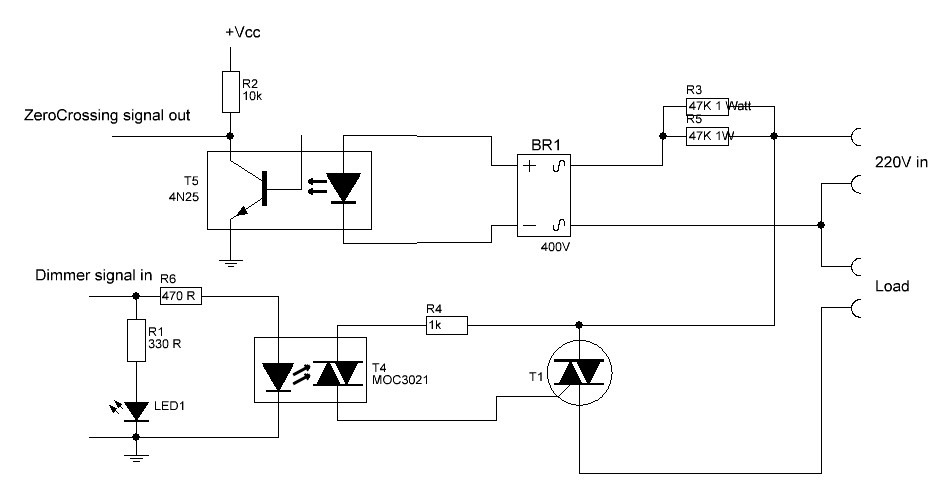
This is a rather classic circuit. It detects the zerocrossing on the grid and then a microcontroller ignites the TRIAC with a time delay that determines the brightness of the attached Lamp. The full cycle is 10mS (at 50Hz)
A circuit like this is easy to make for very low cost (1-2 Euro).
 However, if you shy away from soldering such a circuit, there are ready made modules available as well:
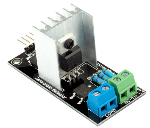 You should not need to pay more than 3-4 USD for such a module. Anything above that is robbery
Software to control this dimmer would look something like this:
#include <Ethernet.h>
#include <PubSubClient.h>
#include  <TimerOne.h>

#define CLIENT_ID       "Dimmer"
#define PUBLISH_DELAY   3000

String ip = "";
bool startsend = HIGH;
uint8_t mac[6] = {0x00, 0x01, 0x02, 0x03, 0x04, 0x07};

volatile int i=0;               // Variable to use as a counter volatile as it is in an interrupt
volatile boolean zero_cross=0;  // Boolean to store a "switch" to tell us if we have crossed zero
int AC_pin1 = 4;// Output to Opto Triac
int dim1 = 0;// Dimming level (0-100)  0 = on, 100 = 0ff

int inc=1;          // counting up or down, 1=up, -1=down
int freqStep = 100; // make this 83 for 60Hz gridfrequency

EthernetClient ethClient;
PubSubClient mqttClient;
long previousMillis;

void zero_cross_detect() {
  zero_cross = true;               // set the boolean to true to tell our dimming function that a zero cross has occured
  i=0;
  digitalWrite(AC_pin1, LOW);       // turn off TRIAC (and AC)
}

// Turn on the TRIAC at the appropriate time
void dim_check() {
  if(zero_cross == true) {
    if(i>=dim1) {
      digitalWrite(AC_pin1, HIGH); // turn on light
      i=0;  // reset time step counter
      zero_cross = false; //reset zero cross detection
    }
    else {
      i++; // increment time step counter
    }
  }
}

void setup() {

  attachInterrupt(0, zero_cross_detect, RISING);    // Attach an Interupt to Pin 2 (interupt 0) for Zero Cross Detection
  Timer1.initialize(freqStep);                      // Initialize TimerOne library for the freq we need
  Timer1.attachInterrupt(dim_check, freqStep);
  pinMode(4, OUTPUT);

  // setup serial communication

  Serial.begin(9600);
  while (!Serial) {};
  Serial.println(F("dimmer"));
  Serial.println();

  // setup ethernet communication using DHCP
  if (Ethernet.begin(mac) == 0) {
    Serial.println(F("Unable to configure Ethernet using DHCP"));
    for (;;);
  }

  Serial.println(F("Ethernet configured via DHCP"));
  Serial.print("IP address: ");
  Serial.println(Ethernet.localIP());
  Serial.println();

  ip = String (Ethernet.localIP()[0]);
  ip = ip + ".";
  ip = ip + String (Ethernet.localIP()[1]);
  ip = ip + ".";
  ip = ip + String (Ethernet.localIP()[2]);
  ip = ip + ".";
  ip = ip + String (Ethernet.localIP()[3]);
  //Serial.println(ip);

  // setup mqtt client
  mqttClient.setClient(ethClient);
  mqttClient.setServer( "192.168.1.103", 1883); // <= put here the address of YOUR MQTT server //Serial.println(F("MQTT client configured")); mqttClient.setCallback(callback); Serial.println(); Serial.println(F("Ready to send data")); previousMillis = millis(); mqttClient.publish("home/br/nb/ip", ip.c_str()); } void loop() { // it's time to send new data? if (millis() - previousMillis > PUBLISH_DELAY) {
  sendData();
  previousMillis = millis();

  }

  mqttClient.loop();
  Serial.print("dim1 in loop = ");
  Serial.println(dim1);
}

void sendData() {
  char msgBuffer[20];
  if (mqttClient.connect(CLIENT_ID)) {
    mqttClient.subscribe("home/br/sb");
    if (startsend) {

      mqttClient.publish("home/br/nb/ip", ip.c_str());
      startsend = LOW;
    }
  }
}

void callback(char* topic, byte* payload, unsigned int length) {
  char msgBuffer[20];

   payload[length] = '\0';            // terminate string with '0'
  String strPayload = String((char*)payload);  // convert to string
  Serial.print("strPayload =  ");
  Serial.println(strPayload); //can use this if using longer southbound topics
  Serial.print("Message arrived [");
  Serial.print(topic);
  Serial.print("] ");//MQTT_BROKER
  for (int i = 0; i < length; i++) {
    Serial.print((char)payload[i]);
  }
  Serial.println();
  Serial.println(payload[0]);

dim1=strPayload.toInt();

}
The value freqStep is usually set at 75 or 78 with this type of circuits, which allows for 128 steps of dimming at 50Hz gridfrequency. I have set the value here purposely to 100 allowing for only 100 steps, which is convenient for use in OpenHAB as the slider goes from 0-100%.
The calculation is as follows:
EDIT 2019 There is a library for the Arduino, the ESP8266 and the ESP32.
50Hz
As we have two zerocrossings per sine wave, the frequency of zerocrossings is 100Hz. Therefore the period between two zerocrossings is 10mSec is 10000uS.
So if you want to have 100 levels of dimming the steps you need to take are 10000/100=100uS
60Hz
The frequency of zerocrossings is 120Hz, therefore the period between two zerocrossings is 8.3mS is 8300uS. So if you want to have 100 levels of dimming, the steps you need to take are 8300/100=83uS -> freqStep=83

Hi, Can you share the name of the ready made module? Can this be used to dim a 220v lamp?
Thanks in advance for your answer.
BR.
https://www.aliexpress.com/item/AC-Light-Dimmer-Module-for-PWM-control-1-Channel-3-3V-5V-logic-AC-50-60hz/32802025086.html
yes can be used with 220 Volt
Thanks for your answer.
Looking at the code I see that you use an interruption PIN but (at least in Arduinos UNO and NANO) interrupts are disabled by SoftwareSerial, that is needed to connect using a ESP8266.
Which arduino did you use for this? or how can you managed to stablish network connection for mqtt without SoftwareSerial?
A solution could be to run this directly on an ESP8266. Do you know if it is possible or only runs on an Arduino board?
Thanks in advance for your answer.
Best regards.
This was on a UNO.
I am not using software serial at all, neither do I use an ESP8266 here, that would be foolish to use just for internet connection. I am using an ArduinoUNO with Ethernetshield here.
As you can see in the code, there is no setup of a software serial, nor are there any AT commands being send to it.
As the ESP8266 is a powerful microcontroller in its own right it would be a waste to use it simply as a connection to Ethernet, but even if you wanted that, there is no need for software serial, hardware serial will do just fine.
I presume it is possible to run the code on an ESP8266, but that is not a ‘solution’ but just another project.
How can display & operating mobile
I am not sure what you are asking
Hello, good project!. Can I replace the 4n25 with the pc817?. I have this in stock.
Thanks in advance.
Best regards.
Sergio, I don’t think that will be a big problem. But can I maybe emphasize that you can buy a ready made board for 3-4 dollars. I am all for DIY, but sometimes it is better to just buy it ready made 🙂
Thanks for reply. You are right, Sometimes I buy ready made modules, they are often cheap and useful and do not justify making them yourself.
This time, I have all the parts in stock so I decided to build it to save time.
But I have somes problems. The first one is when I connect the 220V supply the 47K resistors turning very hot (with or whithout load). Second, at the output of bridge I measure no more than 1.3V, never detect the zero cross signal.
I have one more question. For the ESP8266, the interrupts are not equal to Arduino. Arduino uses the Ticker library and is not supported by the ESP8266. I’m right?. Greetings and thanks again.
Sergio, I fully understand, I sometimes do the same.
The heat dissipated by the 47k resistors is not depending on the load, they merely drive the zerocross detector.
Roughly 5mA will flow through each resistor, which amounts to abt 1 Watt.
The value of these resistors, and thus the powerdissipation is a bit between a roc and a hard place as you could increase them, but at a certain point that will lead to the zerocross pulse becoming wider. Feel free though to experiment with a higher value.
I am not sure how you measured the output. If just with a voltmeter it is higly unlikely that you could measure any difference as the pulses come by with 100-120 pulses/second, so what you will see on a standard multimeter will be anaverage voltage.
You are right about the ESP8266, interrupts but I dont think that has anything to do with the ticker library. The Arduino has hardware interrupts.
The Tickerlibrary works both on Arduino as on ESP afaik https://github.com/esp8266/Arduino/blob/master/libraries/Ticker/examples/TickerBasic/TickerBasic.ino
I have recently got the pre mqtt version working, thank you very much and am now stumbling around this new version (still trying to understand mqtt configuration).
im getting syntax formatting errors when trying to compile this, having only added my cloudmqtt server and ports..
im sure it’s a school boy error, yet for tonight at least stuck..
thanks for getting me this far.
Which PubSub library did you use?Let me get this straight, so I understand. Before you changed the MQTT server and port, did the code compile then?
I copied the code from this post and tried myself. I was surprised to see I got similar compilation errors and i didnt immediately se where the problem was, although I have a hunch:
Wordpress is pretty bad at posting code, it easily changes UTF characters into other characters and I suspect that is where the problem might be.
So…went looking for my original code… but that sadly was on a crashed computer. Fortunately I remembered having sent it to someone and I found that back.
It does contain some code you may not immediately need, but it does dim with the MQTT subject “home/br/sb” Payload being a number
If you leave me your email (I will not make that post public) I can send it to you, as for now it takes me a bit too much time to see where exactly the problem is with the corrupted code
Hello,
I copied the code from this site as well, and it wasn’t compiled. Compile Error 1.
I found, that in the code here the Void Loop part is missing i.e. incorrect.
After inserting the correct Void Code it is compiled now.
Thank you for pointing that out. Sadly wordpress is not great in showing code and i have had pieces of code disappear before. That’s why i now mainly put it on github or gitlab
reported errors are
estMQTT_WORKING_AC_DIMROBOTDYN3.ino.ino:88:3: error: ‘mqttClient’ does not name a type
mqttClient.loop();
^
testMQTT_WORKING_AC_DIMROBOTDYN3.ino.ino:89:3: error: ‘Serial’ does not name a type
Serial.print(“dim1 in loop = “);
^
testMQTT_WORKING_AC_DIMROBOTDYN3.ino.ino:90:3: error: ‘Serial’ does not name a type
Serial.println(dim1);
^
testMQTT_WORKING_AC_DIMROBOTDYN3.ino.ino:91:1: error: expected declaration before ‘}’ token
}
hello…is it possible to adapt that module to support charges up to 30A?
That all depends on the TRIAC you are using
Sir, Please give me the list of all components required. what is BR1, T1, T4, T5 etc?
Thank you.
The components are in the circuit. The BR is a rectifier bridge. T1,T4andT5 are 2 optocouplers and a TRIAC.
As you see a bit unfamiliar with circuits, may I suggest you buy the ready made madule at AliExpress or banggood. It is really cheap
I am interested in using this in Home Assistant or OpenHab, which have MQTT Light components.
Do you know how easily it would integrate? Also, I am interested in a copy of the uncorrupted code also.
Thanks.
Quite easy. The dimming steps are made to be a 100 so can use it with the slider in openhab.
Leave me yr email a d I see if I can find and send you the code
Hi E! I was wondering whether i could also see the code you used for OpenHab integration. I would really appreciate it.
Yousuf
I didnt put it in OpenHab, but you would do it like this:
Sitemap
Slider item=lampbrightness
Items
Dimmer lampbrightness “Lamp” (Light) {channel=your MQTT channel}
your MQTT channel would depend on the topic you use and on wether you are using version or version 2 of the MQTT binding
Thanks for the help! i really appreciate it! 🙂
My pleasure.
Hello,
I have got the dimmer module but it doesn’t quite dimm my lamp with this sketch.
The lamp is always like 100% on, no matter what dim value is used, but on full dim (100), it is completely off.
The onboard LED however seems to dimm just fine, corresponding to the value.
Any idea what this could be? I tried multiple timerone libraries and have no clue that it could be.
Other approaches with delays dimm the lamp just fine, but i like a solution without delays.
On first instance that sounds like a faulty module. It could be that your interrupt isn’t working, but the behaviour of the led is weird. Let’s try to isolate the fault. Could you try and load the testing software from the earlier article so we can see if the fault is with the module or with the code
I have a second module to test if the fault lies there. Just weird that the other approaches with the delay work just fine.
I’ll try out the code from the earlier article this evening and report back.
Did you mean “Dimmer-Arduino” or “AC dimming with PWM and Arduino”?
I did not mention I was running an arduino uno and stripped out without the ethernet and client functionality. But I am going to try the original code on nodmcu too.
Dimmer Arduino. The TRIAC can’t do pwm
witch pin of the uno do you use
Pin 2 for interrupt, pin 4 for output
Unable to compile the code given above..can you pls mail it to me? I am using ESP8266 Node MCU and RObodyn AC Dimmer.
What seems to be the problem?
Hi, Is there any reason why you choose a NODEMCU ?
Can it be done with an ESP01 or an ESP12?
I think any digital pin is enough for output but I don´t know what is needed for interrupt.
Simply because I have it at hand and it is easy to use. ESP01 or ESP12 can do the same. The nodeMCU is just a board with an ESP12 on it. So for the ESP12 you can use the same pin I have used in the nodeMCU and in the ESP01 it is your choice
how we can use this code with nodemcu?
i would like to control it in domoticz, but i need an nodemcu as device, can you help me? thanks
This article describes es how to do it with an ethernet card. For the nodemcu you need to change the ethernet connection to a wifi connection . I do not k ow the ins and outs of domoticz, but if it can work with mqtt then you dont need to do much more
i’m a newbee on that.
it means that i simpy have to change this part of the code:
#include
#include
#include
#define CLIENT_ID “Dimmer”
#define PUBLISH_DELAY 3000
String ip = “”;
bool startsend = HIGH;
uint8_t mac[6] = {0x00, 0x01, 0x02, 0x03, 0x04, 0x07};
with:
#include
#include
#include
#include
#define CLIENT_ID “Dimmer”
#define PUBLISH_DELAY 3000
// WIFI
const char* WIFI_SSID = “MySSID”;
const char* WIFI_PWD = “Mypwd”;
/// Webserver init
ESP8266WebServer server ( 80 );
and i heve to remove:
String ip = “”;
bool startsend = HIGH;
uint8_t mac[6] = {0x00, 0x01, 0x02, 0x03, 0x04, 0x07};
that’s correct?
Yes, only the connection to internet part.
But you do understand that you need an mqtt broker to send the mqtt messages right?
If that is not what you wand you need to program your esp e.g. as a webserver that takes input from either a slider or a box
hi, what i would like to implement is: dimmering a 230V AC light.
I would like to use a nodemcu and domoticz (mqtt broker or simply http command are avaliable)
the best could be a simple wall switch (on/off) connected to nodemcu to switch on/off the light and dimmering the light sliding the dummy device in domoticz.
anyway i try to implement the change inside your script but i recevie error on compiling with arduino 😦
What error?
ATTENZIONE: la libreria TimerOne dichiara di funzionare sulle architetture (avr) e potrebbe non essere compatibile con la tua scheda che utilizza l’architettura (esp8266)
robodyntimer:7:1: error: stray ‘\342’ in program
const char* WIFI_SSID = “NETGEAR”;
robodyntimer:7:1: error: stray ‘\200’ in program
robodyntimer:7:1: error: stray ‘\234’ in program
robodyntimer:7:1: error: stray ‘\342’ in program
robodyntimer:7:1: error: stray ‘\200’ in program
robodyntimer:7:1: error: stray ‘\235’ in program
robodyntimer:8:1: error: stray ‘\342’ in program
const char* WIFI_PWD = “133XXXXX”;
robodyntimer:28:1: error: ‘EthernetClient’ does not name a type
EthernetClient ethClient;
C:\Users\Marco\Desktop\robodyntimer\robodyntimer.ino: In function ‘void setup()’:
robodyntimer:55:10: error: ‘class TimerOne’ has no member named ‘initialize’
Timer1.initialize(freqStep); // Initialize TimerOne library for the freq we need
robodyntimer:56:10: error: ‘class TimerOne’ has no member named ‘attachInterrupt’
Timer1.attachInterrupt(dim_check, freqStep);
robodyntimer:67:7: error: ‘Ethernet’ was not declared in this scope
if (Ethernet.begin(mac) == 0) {
robodyntimer:74:18: error: ‘Ethernet’ was not declared in this scope
Serial.println(Ethernet.localIP());
robodyntimer:87:24: error: ‘ethClient’ was not declared in this scope
mqttClient.setClient(ethClient);
robodyntimer:89:12: error: ‘sendData’ was not declared in this scope
sendData();
C:\Users\Marco\Desktop\robodyntimer\robodyntimer.ino: At global scope:
robodyntimer:94:3: error: ‘mqttClient’ does not name a type
mqttClient.loop();
robodyntimer:95:3: error: ‘Serial’ does not name a type
Serial.print(“dim1 in loop = “);
obodyntimer:96:3: error: ‘Serial’ does not name a type
Serial.println(dim1);
robodyntimer:97:1: error: expected declaration before ‘}’ token
}
exit status 1
stray ‘\342’ in program
The stray codes are there because you copied wrongly from website causing e.g. regular quotes transformed into ‘pretty quotes’. Most likely around NETGEAR
it seams that is not compatible the library timerONE with esp8266, that’s correct?
this is my code added:
#include
#include
#include
#include
// WIFI
const char* WIFI_SSID = “NETGEAR”;
const char* WIFI_PWD = “13XXX”;
/// Webserver init
ESP8266WebServer server ( 80 );
#define CLIENT_ID “Dimmer”
#define PUBLISH_DELAY 3000
String ip = “”;
bool startsend = HIGH;
uint8_t mac[6] = {0x00, 0x01, 0x02, 0x03, 0x04, 0x07};
thanks
when i copy paste the code the editor seams that cut the “<" character. i'll try to write here without
#include ESP8266WiFi.h
#include ESP8266WebServer.h
#include PubSubClient.h
#include TimerOne.h
I dont know what you mean
i do not know if it’s only a problem of my internet brawser but when i copy/paste here the modified code, after the include i show nothing (intead of for example ESP8266WiFi.h) so i write here without the character “” between ESP8266WiFi.h
maybe it’s just a metter of visualization of my internet brawser.
If you post code on a web browser the fishhooks around the library name are interpreted as html code
yes, i think that you are fully right on this.
i remove the fishhooks to make it visible.
let me know if you have some solution to obtain what i need 🙂
as you can see i’m not so skilled on programming
thanks for supporting
What was the compilation error?
You may want to have a look at the code used here https://www.instructables.com/id/Light-Switch-Fan-Dimmer-in-One-Board-With-ESP8266/
Hello thank you for this compehensive tutorial. Can this code work for with esp32 h
There is a general library withexamples that are supposed to work with arduino, esp8266 and esp32
and there is a specific ESP32 library
https://github.com/RobotDynOfficial
Hi!, Thanks for sharing your great work with us.
Have you tried this schematic wih Tasmota or ESPHome?, my goal is to make it work on a Wemos D1 Mini (similar to NodeMCU) with Google Home integration and have it displayed in the Google Home App as dimmerable light.
I’m trying to make my life harder fighting with this kind of things 😛
Sergio i have not tried it with those 2 as it was with a regular ethernet connection on a UNO. Bjt i see no reason why it could not work on a wemos or nodemcu.
I do not know the full ins and outs from Tasmota and esphome but i do not think those are registered within GoogleHome