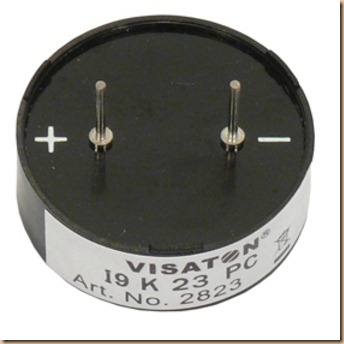
 For a project –that I will publish in the future- I needed some form of audio indication, a warning signal if you please.
I had a small 8 Ohm 0.7 Watt speaker, but that needs a resistor to be connected to the arduino pins to prevent too much current being drawn. Even if a max current of 40 mA would flow through the speaker (with a 242 ohm serial resistor) that would produce a sound at a 128mW level. Not really loud. Add to that that ideally also a capacitor needs to be used to protect the speaker from DC, that will seriously limit its use as a warning signal.
 Of course I could use an amplifier, such as an LM386 (that conveniently can deliver 0.7Watt) or just a 1 transistor amplifier, but I figured a buzzer might be the best solution. Piezzo buzzers are quite commonplace, but I remembered that I still had an unused buzzer that I bought perhaps 30 years ago and never used. That buzzer turned out to be better than I could have hoped for.
I would be hesitant to attach a buzzer directly to a pin of the arduino, so I considered ofcourse using a transistor. s it turned out, I did not need one.
The old buzzer that I had for some reason that I did not understand when I bought it, needed two pins to be tied to ‘+’ and one to the ‘–’.
The buzzer was a CBM-06 from Star industries and a quick search showed that it was only recently discontinued. Out of curiosity I started to look for a datasheet and luckily found some info hidden in another buzzer datasheet.
The CBM-06 seemed to operate on 3-8 volts and its average current draw is 23 mA. However, it needs at least 2-3 times that amount to be available for peak draw and 70mA is just too much for the arduino pins, so I already saw me use a transistor again. Luckily however, I caught a small applicationsheet that proved to be quite helpful. It is pretty loud as it has an output of 76 decibel at 10 cm.
The applicationsheet (if one may call it that way), finally explained to me why I had to connect 2 legs of the buzzer to ‘+’. One of the legs turned out to e a ‘control’ pin. Foratunately, some 30 years ago I had scratched the pins to use in the casing, so I still could see what the function of the pins was.
The middle figure (no 10) in the above picture caught my interest as I figured the ‘control’ pin needed a lot less current to activate the buzzer than the 23-70mA current draw for producing the sound.
So I made a quick setup: + and – connected to the proper supply lines and then 5 Volts fed into the C pin. That worked as I had expected ofcourse because that is how I always had used it.
However, connecting the C pin via a 330 ohm resistor worked as well, proving that a much smaller current suffices to trigger the Buzzer than the 23-70 mA to produce the sound, as only a maximum of 3 mA will flow from the Arduino pin, while the main current is taken directly from the supply line.


